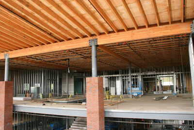
Glulam Beam Design Tables
APA – The Engineered Wood Association provides glulam design tables that provide allowable load capacities and section properties for glulam beams across a wide range of residential, commercial, and industrial applications. These engineering design tools allow designers and specifiers to size members precisely for the structural conditions of their project, going well beyond basic sizing guides to address the full range of spans, loads, species, stress classes, and service conditions encountered in practice.
View Tables
For complete section properties, load-span tables, cantilever beam tables, volume factors, and worked design examples, download APA publication Glued Laminated Beam Design Tables, Form S475.
Glued Laminated Beam Design Tables
For garage door header sizing tables, residential camber reference data, reference design values across all stress classes, and additional design guidance, download APA’s Glulam Product Guide, Form X440, Glulam Garage Door Headers Offer Design Options, Form C410 or Glulam in Residential Building, Form X450.
Glulam Product Guide
Glulam Garage Door Headers Offer Design Options
Glulam in Residential Building
How the Design Tables Work
The design tables calculate allowable loads based on bending strength, horizontal shear strength, and deflection limits—with the controlling design value being the lowest among these three criteria. Tables provide values for a range of beam widths and depths across spans from 8 to 52 feet or more, depending on species and beam size. Load duration factors are applied based on load type: 1.25 for non-snow roof loads, 1.15 for snow loads, and 1.00 for floor loads. Deflection limits of L/180 under total load apply to roof beams; L/360 under live load applies to floor beams. All tabulated values are based on dry service conditions and include beam self-weight in the load totals.
Available Tables
Tables are organized by species, stress class, and application:
24F Douglas-Fir — Section Properties & Capacities — Bending moment and shear capacities for beam widths from 3-1/8 to 8-3/4 inches and depths from 6 to 45 inches (Form S475, Table 1)
24F Douglas-Fir — Simple Span Roof Beams, Non-Snow Loads — Allowable loads for load duration factor of 1.25 (Form S475, Table 2)
24F Douglas-Fir — Simple Span Roof Beams, Snow Loads — Allowable loads for load duration factor of 1.15 (Form S475, Table 3)
24F Douglas-Fir — Simple Span Floor Beams — Allowable loads for load duration factor of 1.00 (Form S475, Table 4)
24F Douglas-Fir — Cantilevered Roof Beams — Allowable loads for three standard cantilever systems under non-snow and snow loads (Form S475, Table 5 &6)
24F Southern Pine — Section Properties, Capacities, and Full Load-Span Table Series — Parallel tables for all roof and floor applications (Form S475, Table 7-12)
Reference Design Values for All Stress Classes (16F through 30F) — Complete design values for bending, shear, modulus of elasticity, tension, compression, and fastener design for both x-x and y-y axis orientations, covering stress classes from 16F-1.3E through 30F-2.1E SP (Form X440, Table 5)
Garage Door Header Sizing Tables — Preliminary design sizing for APA 24F-1.8E grade glulam headers for single-story applications, covering rough door openings of 9'-3" and 16'-3" across a range of supported roof truss spans and load conditions, for both 1-1/2" and 1-3/8" lamination thicknesses (Form X440, Tables 2A and 2B)
Residential Camber Reference Table — Quick-reference camber values for a 5,000-foot radius across spans from 10 to 28 feet, suitable for most residential applications (Form X440, Table 1)
Volume Factor Appendices — CV adjustment factors for Douglas-fir and Southern Pine across all standard beam sizes and spans (Form S475)
Related Design Publications
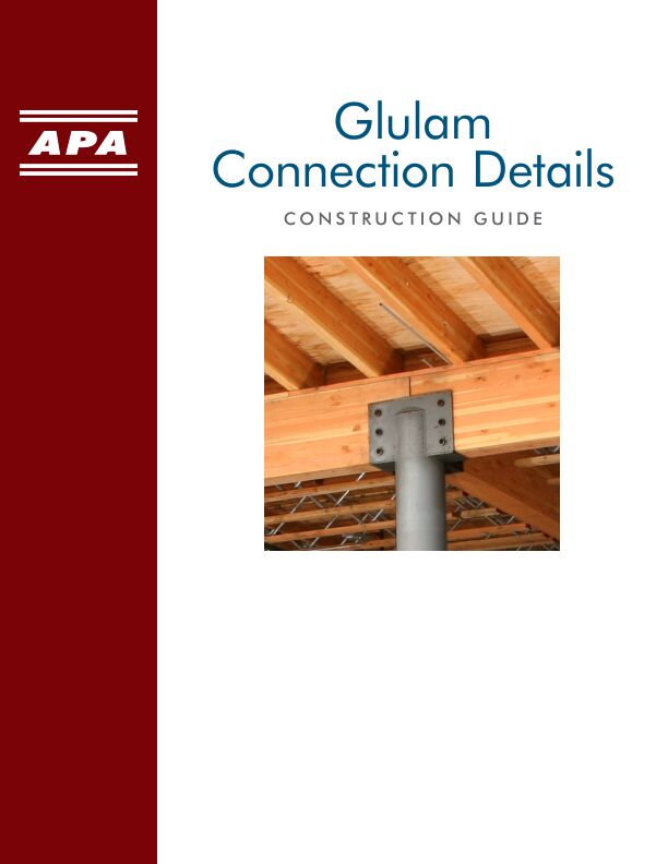
For applications beyond beam design, APA publishes Design of Structural Glued Laminated Timber Columns, Form Y240, which covers axially loaded glulam column design.
All tabulated values must be adjusted for other service conditions, load durations, or stress combinations per the applicable building code. Final design should always include a complete analysis—including bearing stresses and lateral stability—performed by a qualified design professional.
 Residential Construction