Technical Document Library
Research-Backed Guidance for Every Project
Research-Backed Guidance for Every Project
 Typical Details
- DT-FR-1
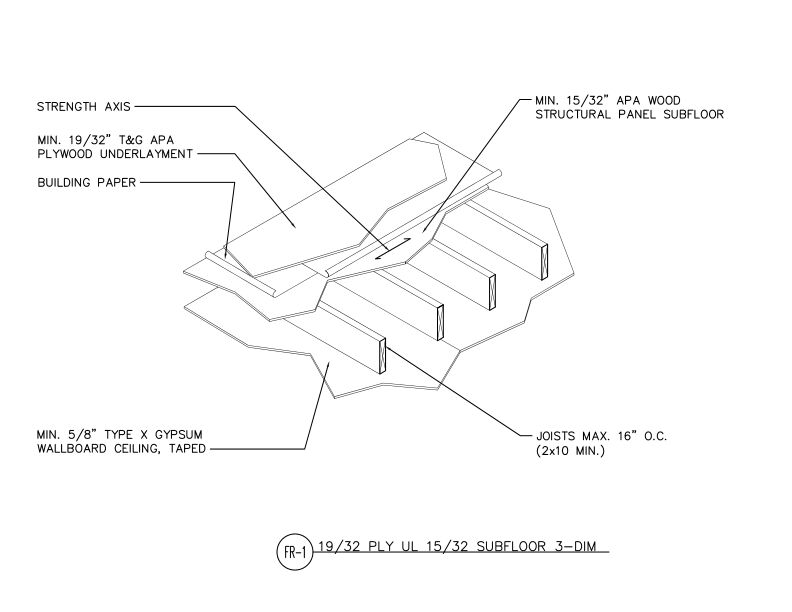
This detail shows floor assembly of APA wood structural panel subfloor over plywood underlayment, building paper, and joists with gypsum wallboard ceiling below.
Typical Details
- DT-FR-1
This detail shows floor assembly of APA wood structural panel subfloor over plywood underlayment, building paper, and joists with gypsum wallboard ceiling below.
 Typical Details
- DT-SPR-1
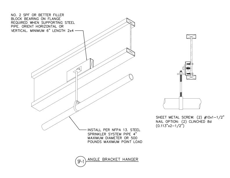
This detail shows angle bracket hanger assembly for supporting steel sprinkler pipe from wood structural members using blocking and optional fastening methods.
Typical Details
- DT-SPR-1
This detail shows angle bracket hanger assembly for supporting steel sprinkler pipe from wood structural members using blocking and optional fastening methods.
 Typical Details
- DT-FR-2
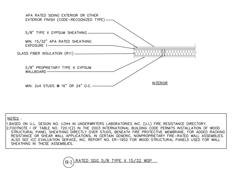
This detail shows a fire-rated wall assembly using wood structural panel sheathing over studs with gypsum wallboard, fire protective membrane, and glass fiber insulation.
Typical Details
- DT-FR-2
This detail shows a fire-rated wall assembly using wood structural panel sheathing over studs with gypsum wallboard, fire protective membrane, and glass fiber insulation.
 Typical Details
- DT-FR-3
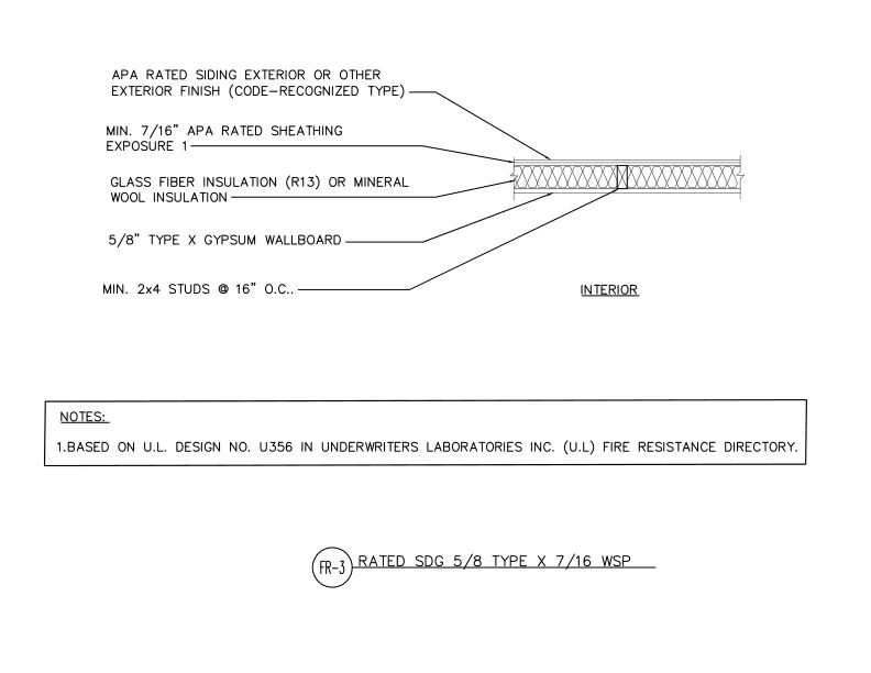
This detail shows fire-rated exterior wall assembly with APA rated siding over sheathing, insulation, 2x4 wood framing at 16" on center and Type X gypsum wallboard interior finish.
Typical Details
- DT-FR-3
This detail shows fire-rated exterior wall assembly with APA rated siding over sheathing, insulation, 2x4 wood framing at 16" on center and Type X gypsum wallboard interior finish.
 Typical Details
- DT-FR-4
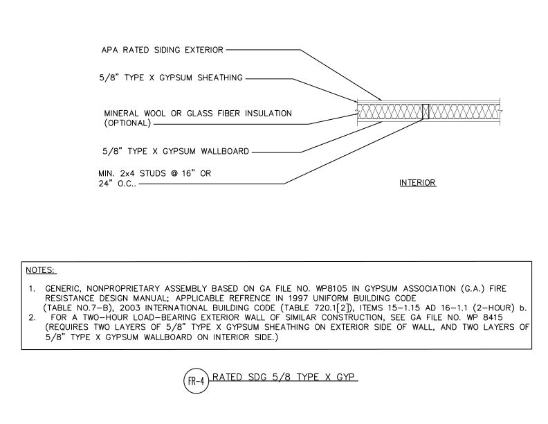
This detail shows a one-hour fire-rated wood-framed wall assembly with Type X gypsum sheathing and wallboard, optional insulation, and APA rated siding exterior finish.
Typical Details
- DT-FR-4
This detail shows a one-hour fire-rated wood-framed wall assembly with Type X gypsum sheathing and wallboard, optional insulation, and APA rated siding exterior finish.
 Typical Details
- DT-SPR-2
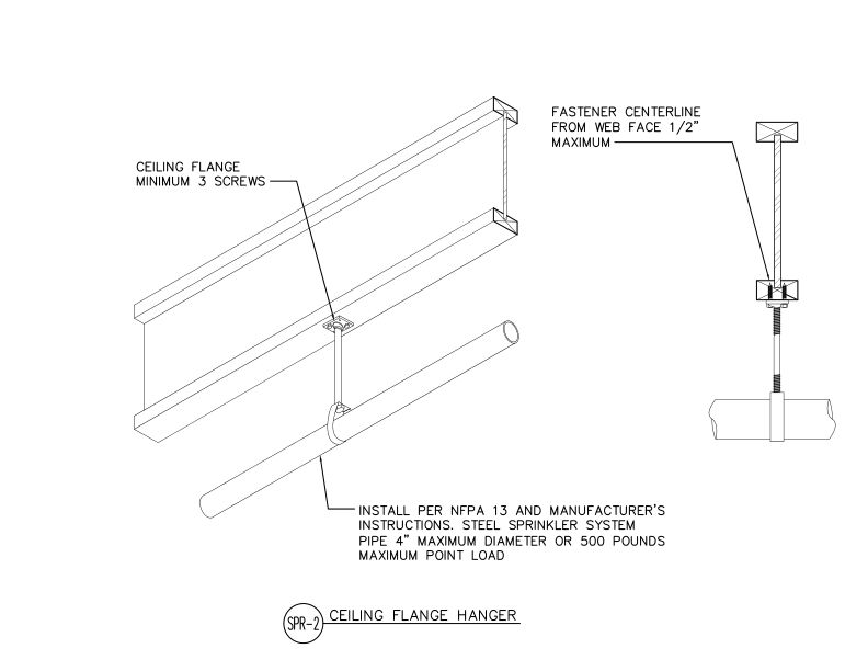
This detail shows ceiling flange hanger installation for supporting steel sprinkler system pipes from engineered wood ceiling joists.
Typical Details
- DT-SPR-2
This detail shows ceiling flange hanger installation for supporting steel sprinkler system pipes from engineered wood ceiling joists.
 Typical Details
- DT-SPR-3
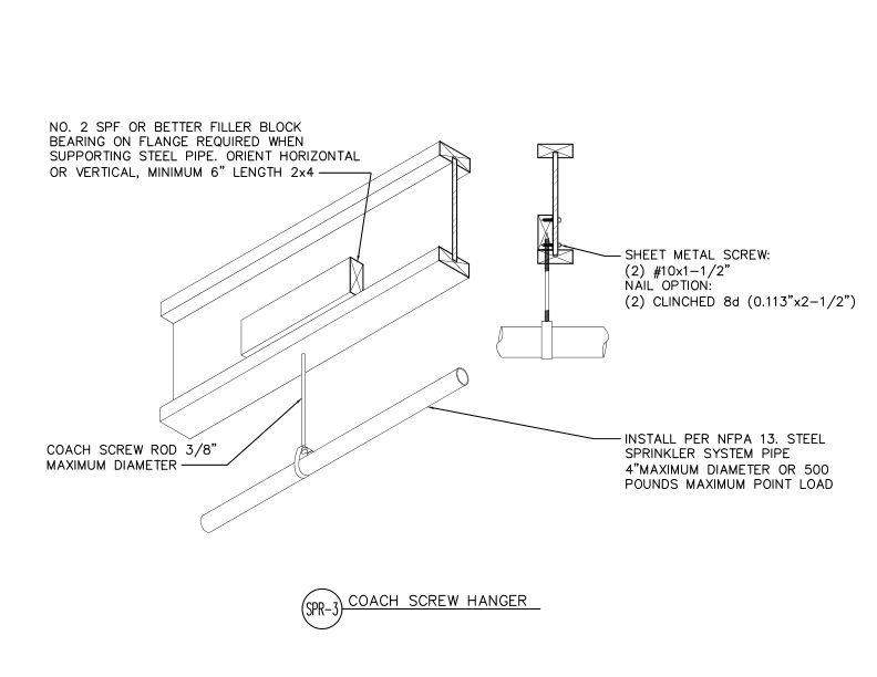
This detail shows a coach screw hanger assembly for supporting steel sprinkler pipe from wood framing using filler blocks and sheet metal screws or nails.
Typical Details
- DT-SPR-3
This detail shows a coach screw hanger assembly for supporting steel sprinkler pipe from wood framing using filler blocks and sheet metal screws or nails.
 Typical Details
- DT-SPR-4
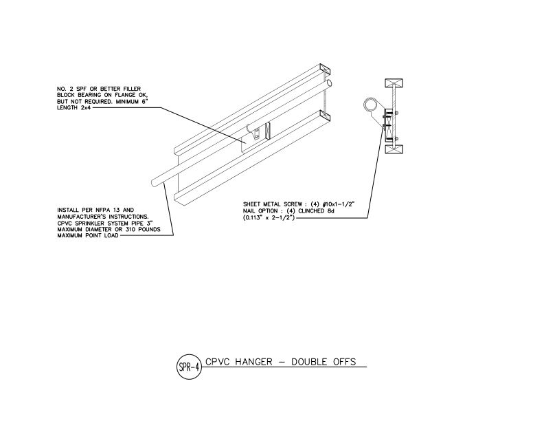
This detail shows double offset CPVC sprinkler pipe hanger assembly using 2x4 blocking with sheet metal screws or nails, supporting 3" maximum diameter pipe per NFPA 13.
Typical Details
- DT-SPR-4
This detail shows double offset CPVC sprinkler pipe hanger assembly using 2x4 blocking with sheet metal screws or nails, supporting 3" maximum diameter pipe per NFPA 13.
 Typical Details
- DT-SPR-5
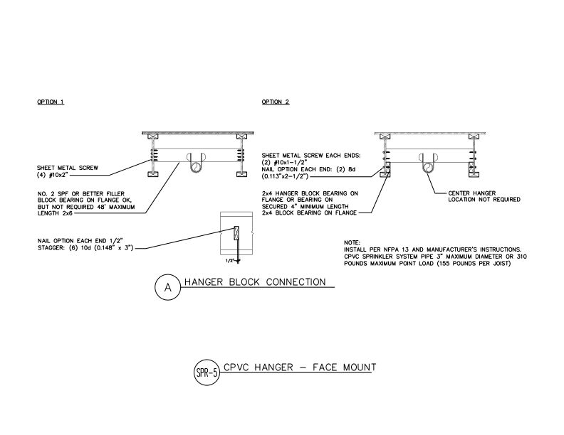
This detail shows two installation options for face-mounting CPVC sprinkler pipe hangers to wood blocking using either sheet metal screws or nail-and-block combinations.
Typical Details
- DT-SPR-5
This detail shows two installation options for face-mounting CPVC sprinkler pipe hangers to wood blocking using either sheet metal screws or nail-and-block combinations.
 Typical Details
- DT-SPR-6
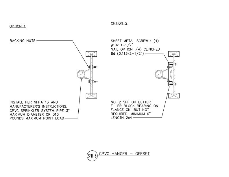
This detail shows offset hanger installation for CPVC sprinkler system pipes showing two attachment options using backing nuts or sheet metal screws with lumber blocking.
Typical Details
- DT-SPR-6
This detail shows offset hanger installation for CPVC sprinkler system pipes showing two attachment options using backing nuts or sheet metal screws with lumber blocking.
 Typical Details
- DT-SPR-7
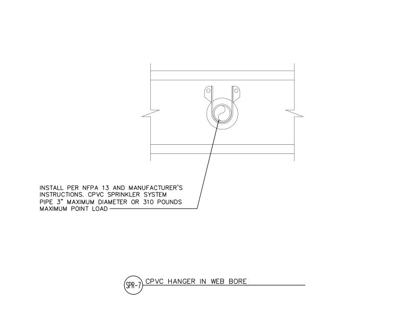
This detail shows proper installation of a CPVC sprinkler system pipe hanger through an I-joist web bore, with maximum diameter and load requirements per NFPA 13.
Typical Details
- DT-SPR-7
This detail shows proper installation of a CPVC sprinkler system pipe hanger through an I-joist web bore, with maximum diameter and load requirements per NFPA 13.
 Typical Details
- DT-SPR-8
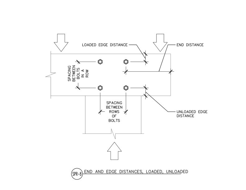
This detail shows proper bolt spacing requirements including loaded edge distance, unloaded edge distance, end distance, and spacing between rows of bolts.
Typical Details
- DT-SPR-8
This detail shows proper bolt spacing requirements including loaded edge distance, unloaded edge distance, end distance, and spacing between rows of bolts.
 Typical Details
- DT-SPR-9
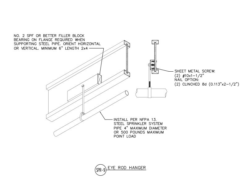
This detail shows eye rod hanger for supporting steel sprinkler pipes from wood framing using filler blocks and sheet metal screws or nails per NFPA 13 requirements.
Typical Details
- DT-SPR-9
This detail shows eye rod hanger for supporting steel sprinkler pipes from wood framing using filler blocks and sheet metal screws or nails per NFPA 13 requirements.
 Typical Details
- DT-FPF-4
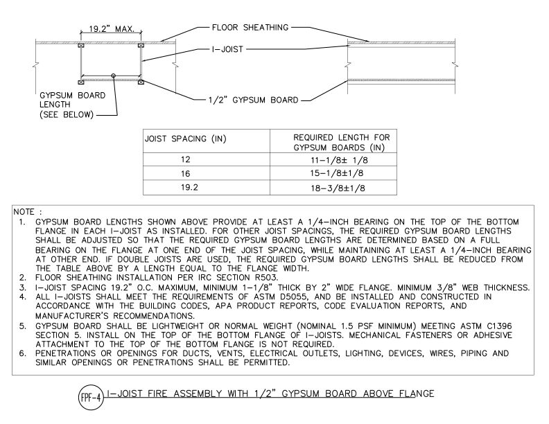
This detail shows an I-joist floor assembly with 1/2" gypsum board placed above the bottom flange for fire protection per IRC Section R503.
Typical Details
- DT-FPF-4
This detail shows an I-joist floor assembly with 1/2" gypsum board placed above the bottom flange for fire protection per IRC Section R503.
 Typical Details
- DT-FPF-5
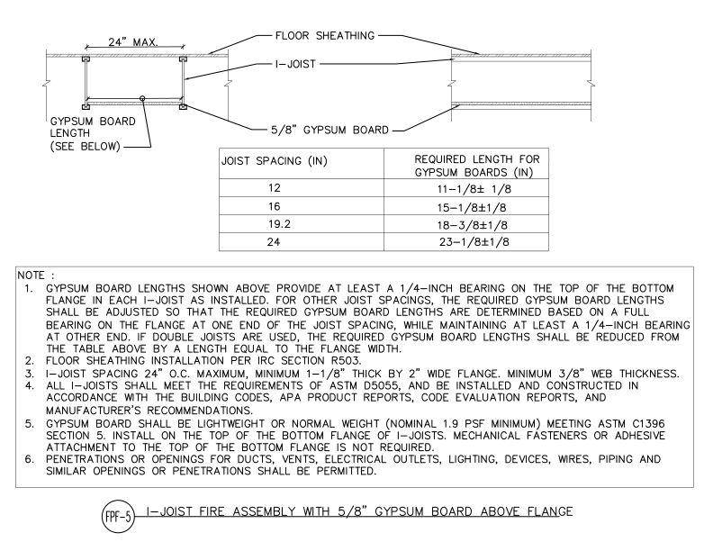
This detail shows an I-joist floor assembly with 5/8" gypsum board placed above the bottom flange for fire protection per IRC Section R503.
Typical Details
- DT-FPF-5
This detail shows an I-joist floor assembly with 5/8" gypsum board placed above the bottom flange for fire protection per IRC Section R503.
 Typical Details
- DT-FPF-2
This detail shows 1/2" gypsum board fastened to the bottom flange of an I-joist floor assembly for fire protection per IRC Section R702.3.1.
Typical Details
- DT-FPF-2
This detail shows 1/2" gypsum board fastened to the bottom flange of an I-joist floor assembly for fire protection per IRC Section R702.3.1.
 Typical Details
- DT-FPF-1
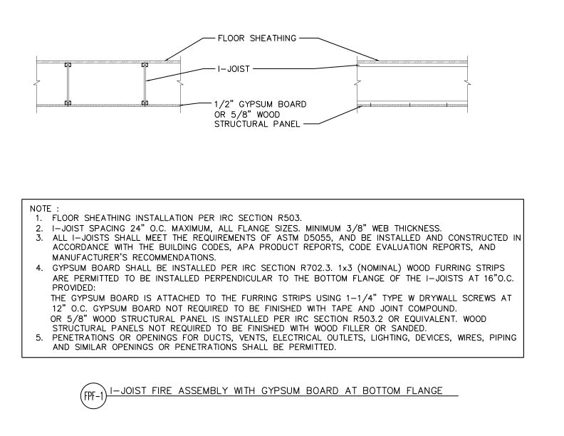
This detail shows 1/2" gypsum board or 5/8" wood structural panel installed at the bottom flange of an I-joist floor assembly for fire protection per IRC Section R702.3.
Typical Details
- DT-FPF-1
This detail shows 1/2" gypsum board or 5/8" wood structural panel installed at the bottom flange of an I-joist floor assembly for fire protection per IRC Section R702.3.
 Typical Details
- DT-FPF-3
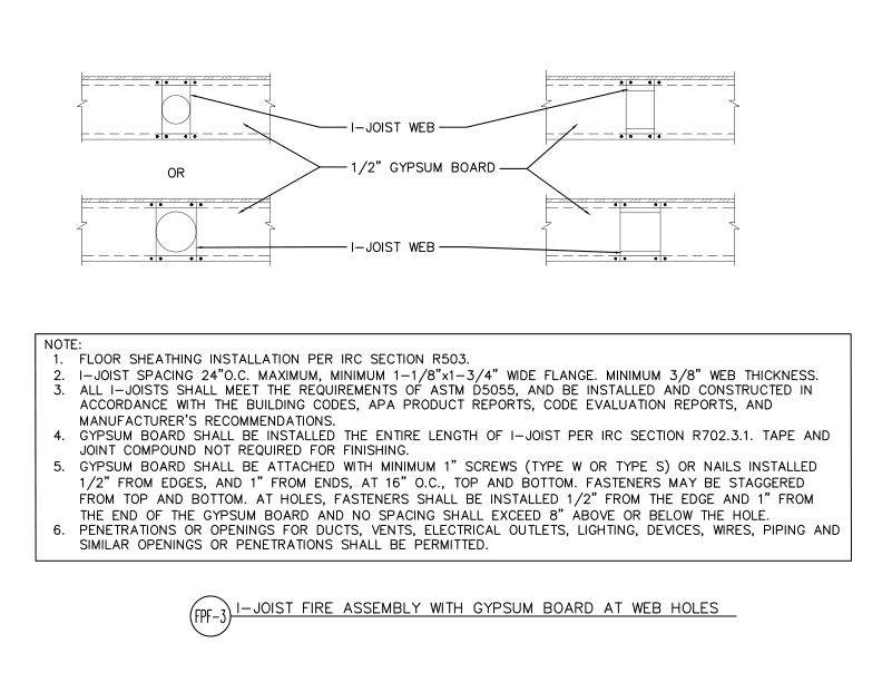
This detail shows 1/2" gypsum board installed at I-joist web holes for fire protection, shown in two configurations per IRC Section R702.3.1.
Typical Details
- DT-FPF-3
This detail shows 1/2" gypsum board installed at I-joist web holes for fire protection, shown in two configurations per IRC Section R702.3.1.
 Typical Details
- DT-FPF-7
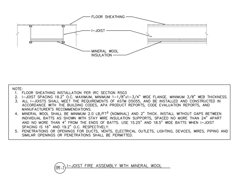
This detail shows an I-joist floor assembly with mineral wool insulation for fire protection per IRC Section R503.
Typical Details
- DT-FPF-7
This detail shows an I-joist floor assembly with mineral wool insulation for fire protection per IRC Section R503.
 Typical Details
- DT-FPF-6
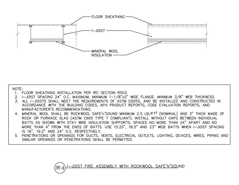
This detail shows an I-joist floor assembly with Rockwool Safe'n'Sound mineral wool insulation for fire protection per IRC Section R503.
Typical Details
- DT-FPF-6
This detail shows an I-joist floor assembly with Rockwool Safe'n'Sound mineral wool insulation for fire protection per IRC Section R503.
 Typical Details
- DT-FR-5
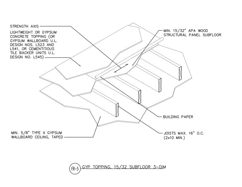
This detail shows three-dimensional floor assembly of APA wood structural panel subflooring with gypsum concrete topping over joists and Type X gypsum wallboard ceiling below.
Typical Details
- DT-FR-5
This detail shows three-dimensional floor assembly of APA wood structural panel subflooring with gypsum concrete topping over joists and Type X gypsum wallboard ceiling below.
 Typical Details
- DT-SPR-11
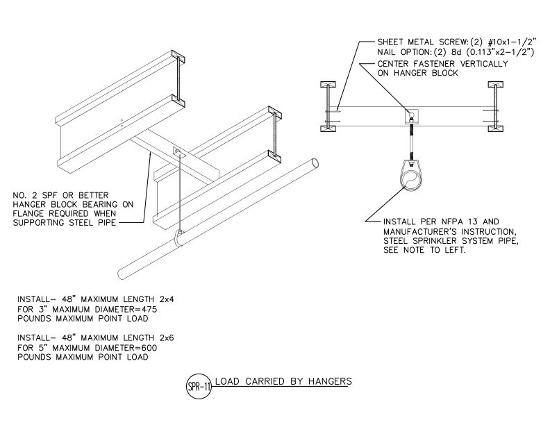
Installation detail for supporting steel sprinkler pipes from structural framing using hanger blocks with fastening specifications for different pipe sizes and loads.
Typical Details
- DT-SPR-11
Installation detail for supporting steel sprinkler pipes from structural framing using hanger blocks with fastening specifications for different pipe sizes and loads.
 Typical Details
- DT-FR-6
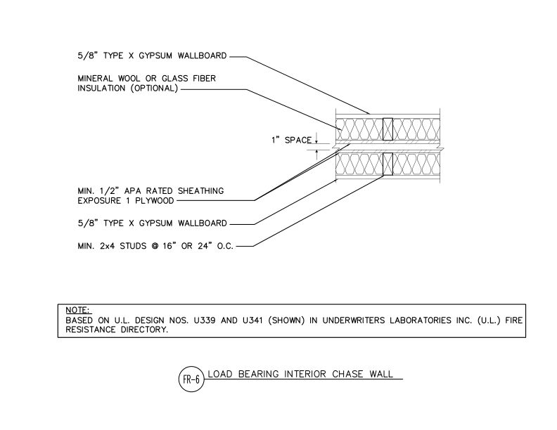
Fire-rated load bearing interior chase wall assembly with gypsum wallboard, plywood sheathing, insulation cavity, and 1-inch space between stud walls at 16- or 24-inch centers.
Typical Details
- DT-FR-6
Fire-rated load bearing interior chase wall assembly with gypsum wallboard, plywood sheathing, insulation cavity, and 1-inch space between stud walls at 16- or 24-inch centers.
 Typical Details
- DT-FR-7
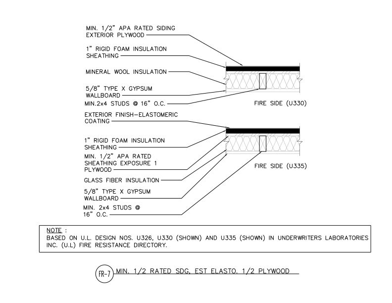
Fire-rated wall assembly of two UL-rated configurations (U330 and U335) with different exterior finishes over wood framing with mineral wool or glass fiber insulation.
Typical Details
- DT-FR-7
Fire-rated wall assembly of two UL-rated configurations (U330 and U335) with different exterior finishes over wood framing with mineral wool or glass fiber insulation.