Technical Document Library
Research-Backed Guidance for Every Project
Research-Backed Guidance for Every Project
 Typical Details
- DT-SPR-1
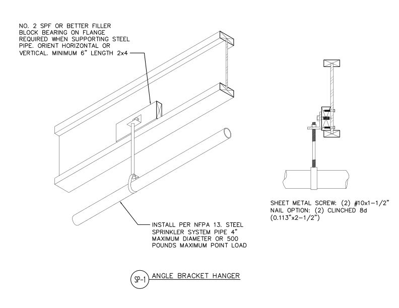
This detail shows angle bracket hanger assembly for supporting steel sprinkler pipe from wood structural members using blocking and optional fastening methods.
Typical Details
- DT-SPR-1
This detail shows angle bracket hanger assembly for supporting steel sprinkler pipe from wood structural members using blocking and optional fastening methods.
 Typical Details
- DT-EWG-4
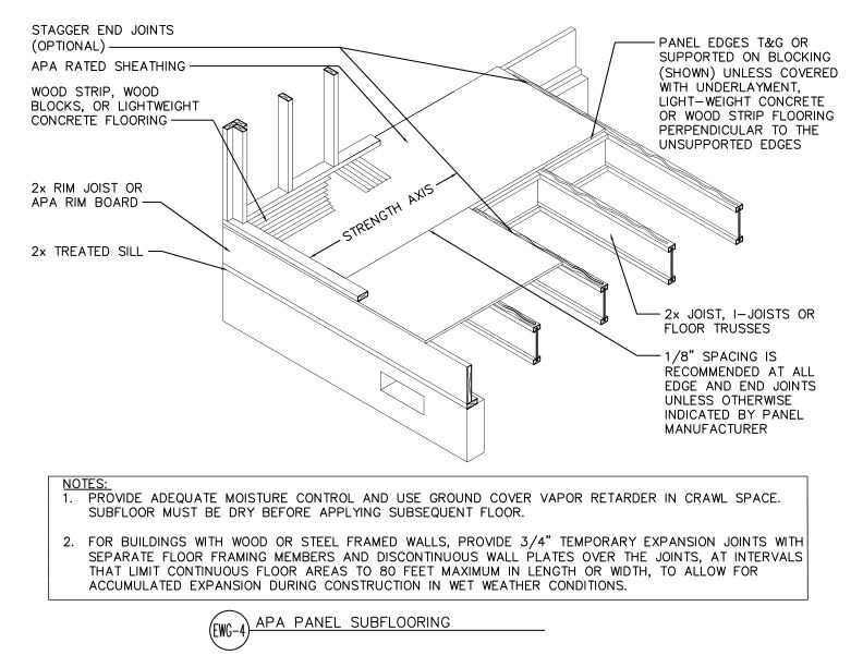
APA Rated sheathing panels installed as subflooring over 2x joists, I-joists, or floor trusses with tongue-and-groove or blocked edges on a wood-framed floor system.
Typical Details
- DT-EWG-4
APA Rated sheathing panels installed as subflooring over 2x joists, I-joists, or floor trusses with tongue-and-groove or blocked edges on a wood-framed floor system.
 Typical Details
- DT-IJ-1
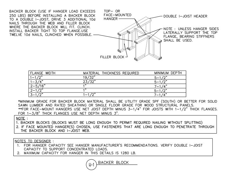
This detail outlines backer block installation for single and double I-joist headers.
Typical Details
- DT-IJ-1
This detail outlines backer block installation for single and double I-joist headers.
 Typical Details
- DT-IJ-2
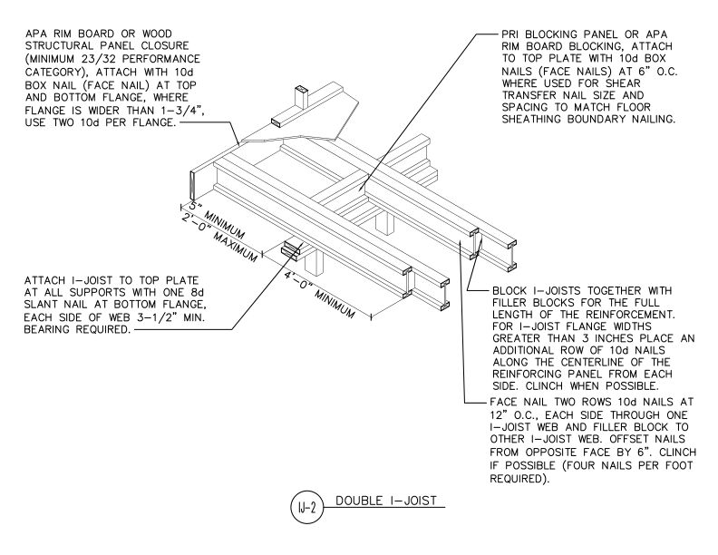
This detail shows cantilevered double I-joists supporting a vertical building offset and specifies connections to the top plate, blocking panels, and Rim Board or APA WSP closure.
Typical Details
- DT-IJ-2
This detail shows cantilevered double I-joists supporting a vertical building offset and specifies connections to the top plate, blocking panels, and Rim Board or APA WSP closure.
 Typical Details
- DT-SPR-2
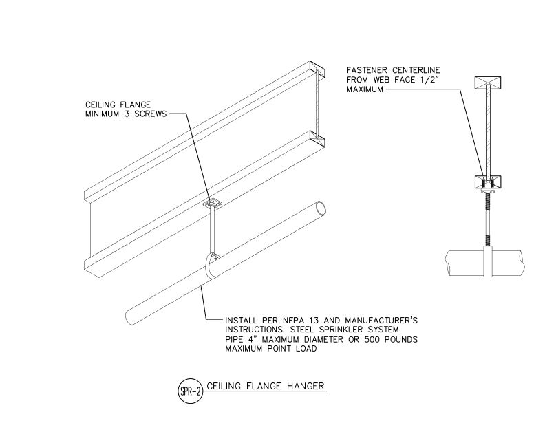
This detail shows ceiling flange hanger installation for supporting steel sprinkler system pipes from engineered wood ceiling joists.
Typical Details
- DT-SPR-2
This detail shows ceiling flange hanger installation for supporting steel sprinkler system pipes from engineered wood ceiling joists.
 Typical Details
- DT-SPR-3
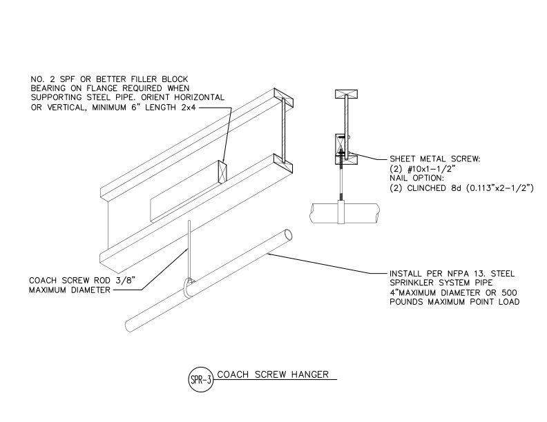
This detail shows a coach screw hanger assembly for supporting steel sprinkler pipe from wood framing using filler blocks and sheet metal screws or nails.
Typical Details
- DT-SPR-3
This detail shows a coach screw hanger assembly for supporting steel sprinkler pipe from wood framing using filler blocks and sheet metal screws or nails.
 Typical Details
- DT-SPR-4
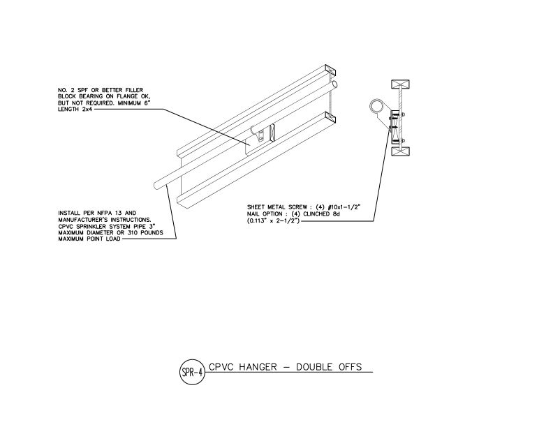
This detail shows double offset CPVC sprinkler pipe hanger assembly using 2x4 blocking with sheet metal screws or nails, supporting 3" maximum diameter pipe per NFPA 13.
Typical Details
- DT-SPR-4
This detail shows double offset CPVC sprinkler pipe hanger assembly using 2x4 blocking with sheet metal screws or nails, supporting 3" maximum diameter pipe per NFPA 13.
 Typical Details
- DT-SPR-5
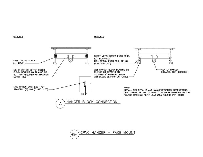
This detail shows two installation options for face-mounting CPVC sprinkler pipe hangers to wood blocking using either sheet metal screws or nail-and-block combinations.
Typical Details
- DT-SPR-5
This detail shows two installation options for face-mounting CPVC sprinkler pipe hangers to wood blocking using either sheet metal screws or nail-and-block combinations.
 Typical Details
- DT-SPR-6
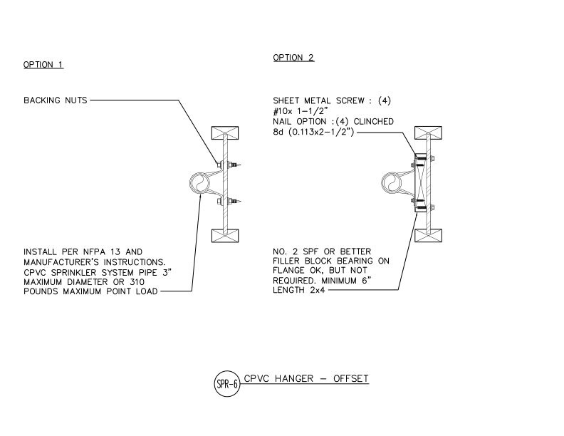
This detail shows offset hanger installation for CPVC sprinkler system pipes showing two attachment options using backing nuts or sheet metal screws with lumber blocking.
Typical Details
- DT-SPR-6
This detail shows offset hanger installation for CPVC sprinkler system pipes showing two attachment options using backing nuts or sheet metal screws with lumber blocking.
 Typical Details
- DT-SPR-7
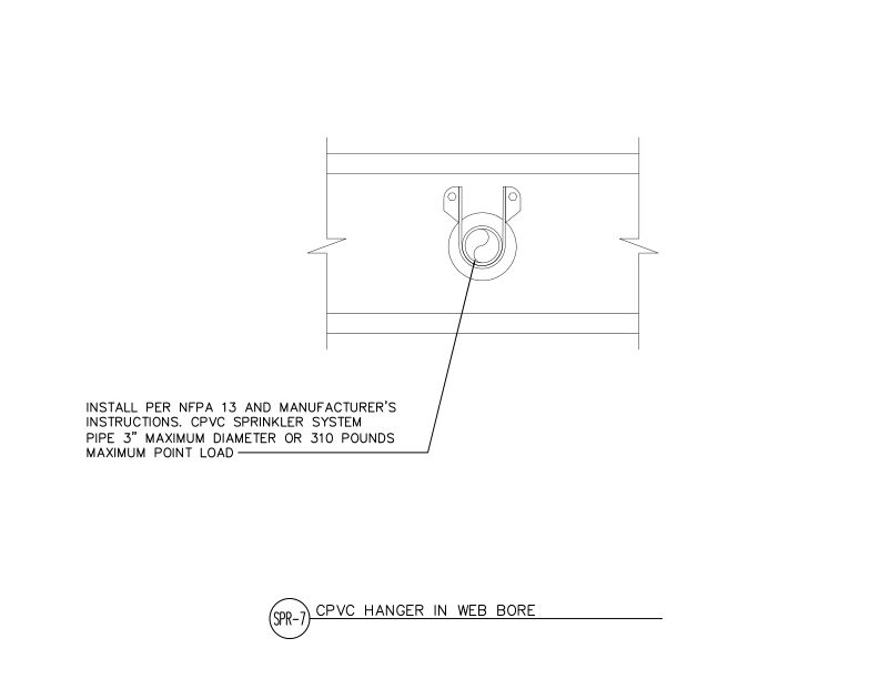
This detail shows proper installation of a CPVC sprinkler system pipe hanger through an I-joist web bore, with maximum diameter and load requirements per NFPA 13.
Typical Details
- DT-SPR-7
This detail shows proper installation of a CPVC sprinkler system pipe hanger through an I-joist web bore, with maximum diameter and load requirements per NFPA 13.
 Typical Details
- DT-SPR-8
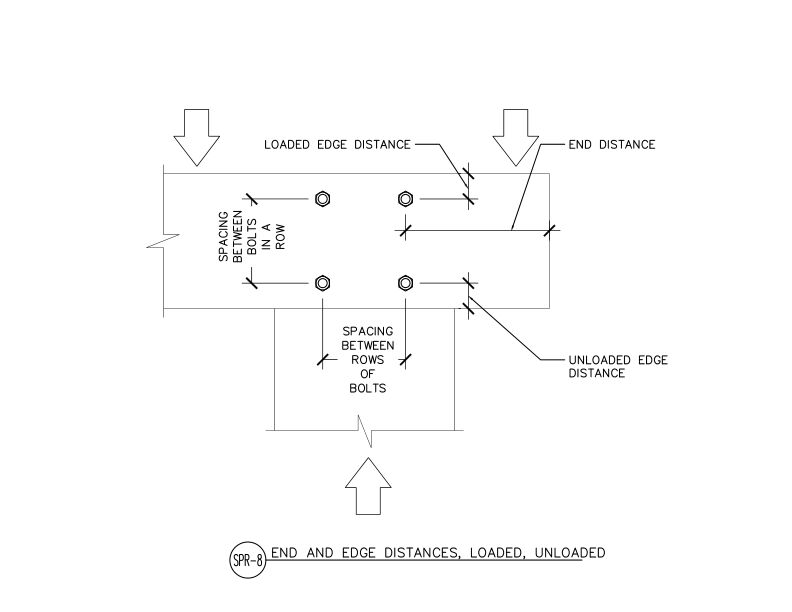
This detail shows proper bolt spacing requirements including loaded edge distance, unloaded edge distance, end distance, and spacing between rows of bolts.
Typical Details
- DT-SPR-8
This detail shows proper bolt spacing requirements including loaded edge distance, unloaded edge distance, end distance, and spacing between rows of bolts.
 Typical Details
- DT-SPR-9
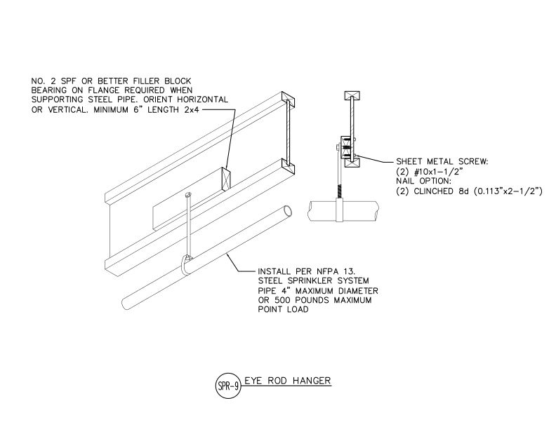
This detail shows eye rod hanger for supporting steel sprinkler pipes from wood framing using filler blocks and sheet metal screws or nails per NFPA 13 requirements.
Typical Details
- DT-SPR-9
This detail shows eye rod hanger for supporting steel sprinkler pipes from wood framing using filler blocks and sheet metal screws or nails per NFPA 13 requirements.
 Typical Details
- DT-EWG-18
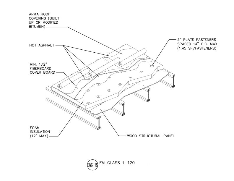
This detail shows an FM Class 1-120 rated flat roof assembly using wood structural panels over steel joists.
Typical Details
- DT-EWG-18
This detail shows an FM Class 1-120 rated flat roof assembly using wood structural panels over steel joists.
 Typical Details
- DT-IJ-3
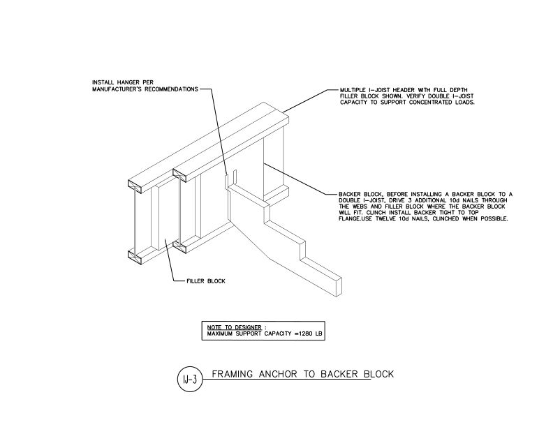
This detail shows installation of backer and filler blocks for a double I-joist header supporting a stair stringer that is attached with a framing anchor.
Typical Details
- DT-IJ-3
This detail shows installation of backer and filler blocks for a double I-joist header supporting a stair stringer that is attached with a framing anchor.
 Typical Details
- DT-IJ-4
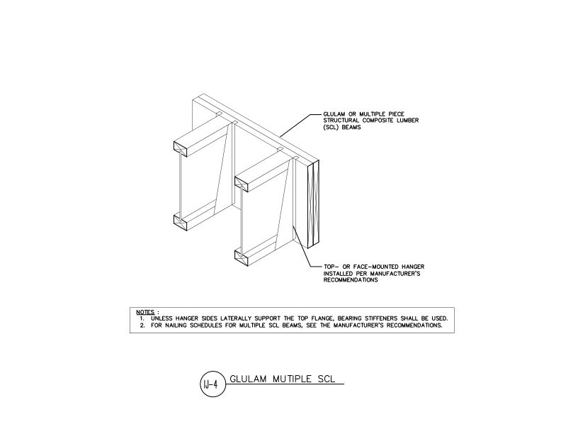
This detail shows I-Joists with top mount hangers supported by a multi-ply structural composite lumber (SCL) beam. This detail is similar for a glulam beam with face mount hangers.
Typical Details
- DT-IJ-4
This detail shows I-Joists with top mount hangers supported by a multi-ply structural composite lumber (SCL) beam. This detail is similar for a glulam beam with face mount hangers.
 Typical Details
- DT-IJ-5
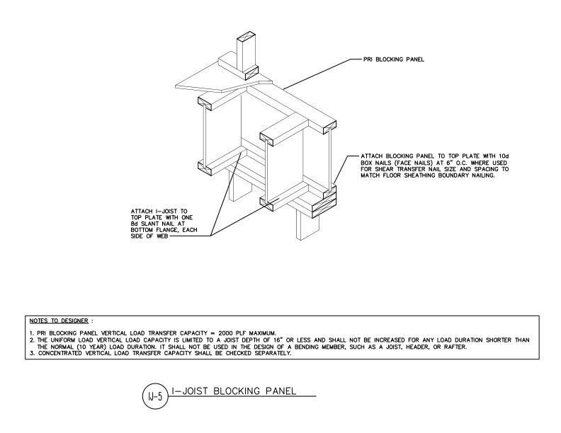
This detail shows the installation of PRI blocking panels between I-joists, attached to top plate with face nails for shear transfer at floor sheathing boundaries.
Typical Details
- DT-IJ-5
This detail shows the installation of PRI blocking panels between I-joists, attached to top plate with face nails for shear transfer at floor sheathing boundaries.
 Typical Details
- DT-IJ-6
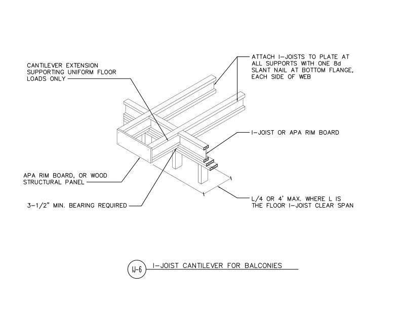
This detail outlines proper construction methods for cantilevered I-joist floor extensions, such as balconies.
Typical Details
- DT-IJ-6
This detail outlines proper construction methods for cantilevered I-joist floor extensions, such as balconies.
 Typical Details
- DT-FPF-4
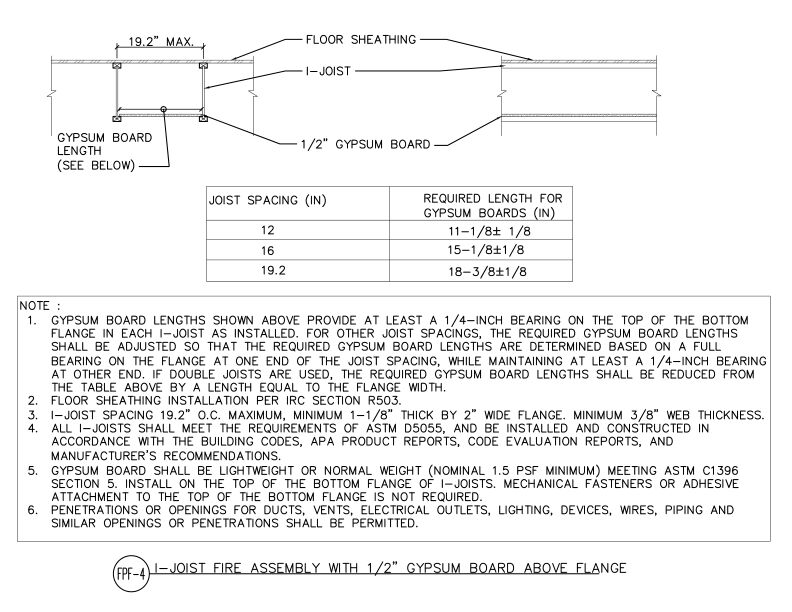
This detail shows an I-joist floor assembly with 1/2" gypsum board placed above the bottom flange for fire protection per IRC Section R503.
Typical Details
- DT-FPF-4
This detail shows an I-joist floor assembly with 1/2" gypsum board placed above the bottom flange for fire protection per IRC Section R503.
 Typical Details
- DT-FPF-5
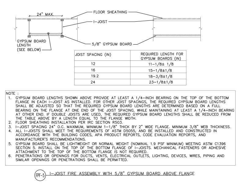
This detail shows an I-joist floor assembly with 5/8" gypsum board placed above the bottom flange for fire protection per IRC Section R503.
Typical Details
- DT-FPF-5
This detail shows an I-joist floor assembly with 5/8" gypsum board placed above the bottom flange for fire protection per IRC Section R503.
 Typical Details
- DT-FPF-2
This detail shows 1/2" gypsum board fastened to the bottom flange of an I-joist floor assembly for fire protection per IRC Section R702.3.1.
Typical Details
- DT-FPF-2
This detail shows 1/2" gypsum board fastened to the bottom flange of an I-joist floor assembly for fire protection per IRC Section R702.3.1.
 Typical Details
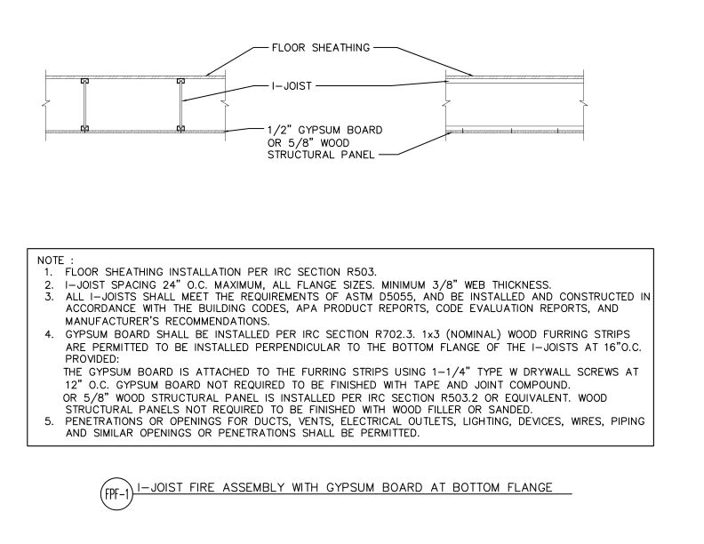
- DT-FPF-1
This detail shows 1/2" gypsum board or 5/8" wood structural panel installed at the bottom flange of an I-joist floor assembly for fire protection per IRC Section R702.3.
Typical Details
- DT-FPF-1
This detail shows 1/2" gypsum board or 5/8" wood structural panel installed at the bottom flange of an I-joist floor assembly for fire protection per IRC Section R702.3.
 Typical Details
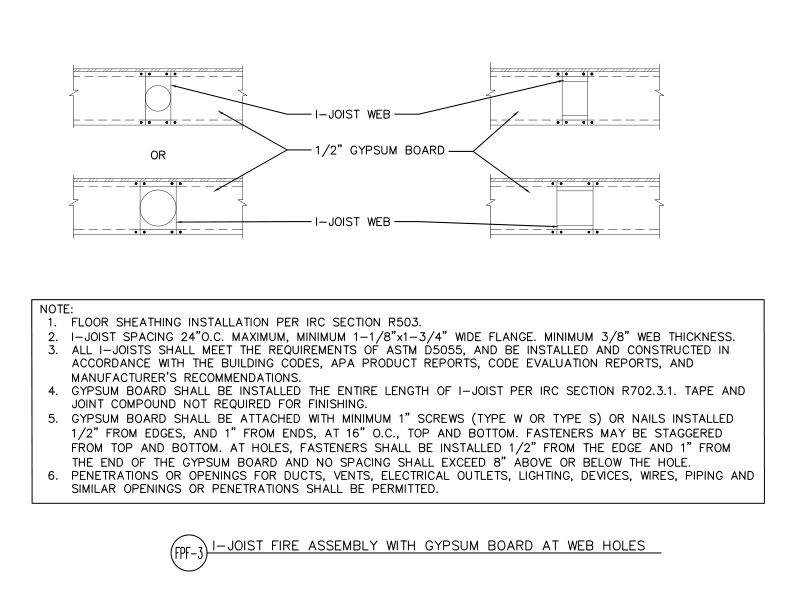
- DT-FPF-3
This detail shows 1/2" gypsum board installed at I-joist web holes for fire protection, shown in two configurations per IRC Section R702.3.1.
Typical Details
- DT-FPF-3
This detail shows 1/2" gypsum board installed at I-joist web holes for fire protection, shown in two configurations per IRC Section R702.3.1.
 Typical Details
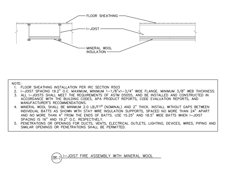
- DT-FPF-7
This detail shows an I-joist floor assembly with mineral wool insulation for fire protection per IRC Section R503.
Typical Details
- DT-FPF-7
This detail shows an I-joist floor assembly with mineral wool insulation for fire protection per IRC Section R503.
 Typical Details
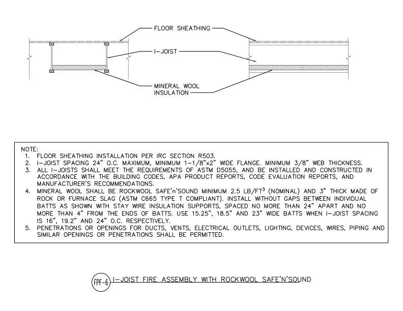
- DT-FPF-6
This detail shows an I-joist floor assembly with Rockwool Safe'n'Sound mineral wool insulation for fire protection per IRC Section R503.
Typical Details
- DT-FPF-6
This detail shows an I-joist floor assembly with Rockwool Safe'n'Sound mineral wool insulation for fire protection per IRC Section R503.