Technical Document Library
Research-Backed Guidance for Every Project
Research-Backed Guidance for Every Project
 Typical Details
- DT-FR-1
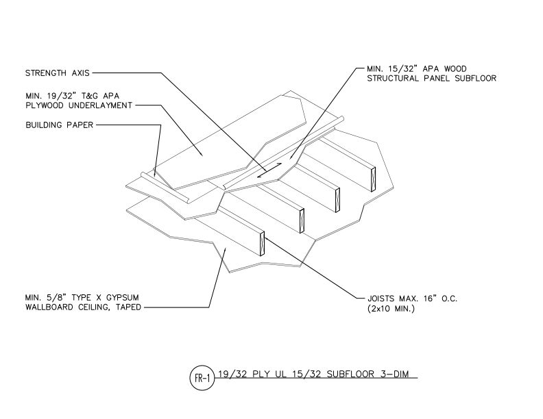
This detail shows floor assembly of APA wood structural panel subfloor over plywood underlayment, building paper, and joists with gypsum wallboard ceiling below.
Typical Details
- DT-FR-1
This detail shows floor assembly of APA wood structural panel subfloor over plywood underlayment, building paper, and joists with gypsum wallboard ceiling below.
 Typical Details
- DT-AF-1
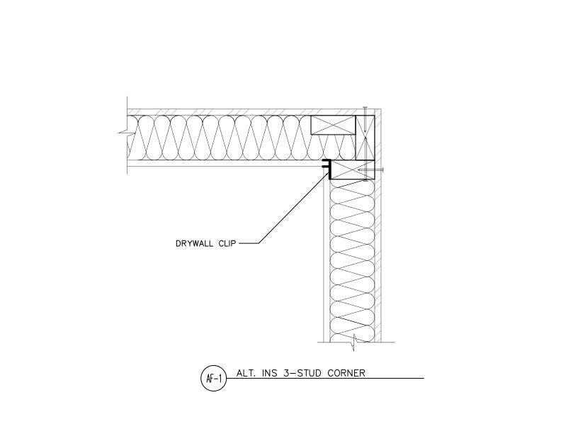
This detail shows an alternative insulated 3-stud corner framing assembly with drywall clips to support the gypsum from one stud.
Typical Details
- DT-AF-1
This detail shows an alternative insulated 3-stud corner framing assembly with drywall clips to support the gypsum from one stud.
 Typical Details
- DT-SPR-1
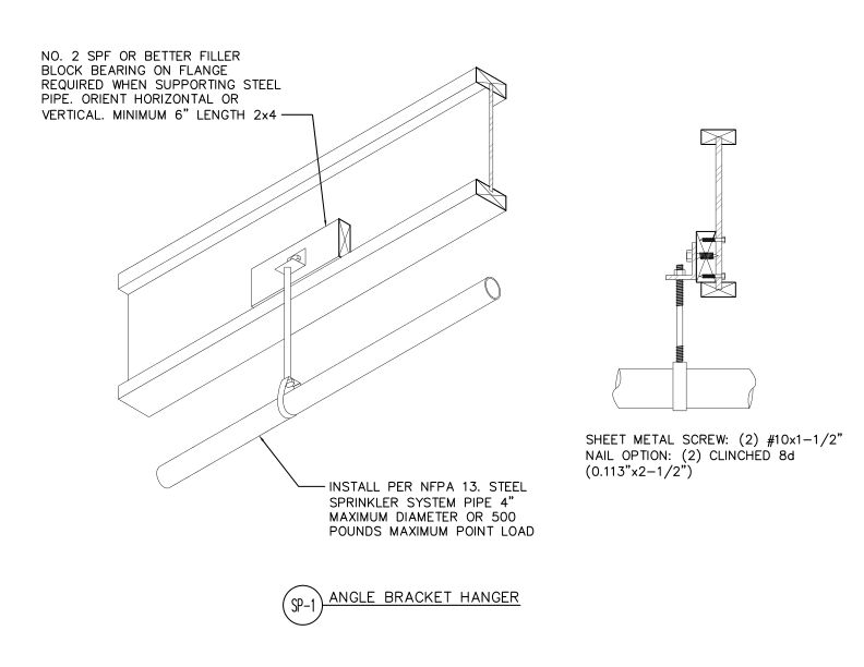
This detail shows angle bracket hanger assembly for supporting steel sprinkler pipe from wood structural members using blocking and optional fastening methods.
Typical Details
- DT-SPR-1
This detail shows angle bracket hanger assembly for supporting steel sprinkler pipe from wood structural members using blocking and optional fastening methods.
 Typical Details
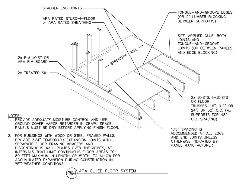
- DT-EWG-1
This detail shows an APA glued floor system using APA Rated Sturd-I-Floor or sheathing panels.
Typical Details
- DT-EWG-1
This detail shows an APA glued floor system using APA Rated Sturd-I-Floor or sheathing panels.
 Typical Details
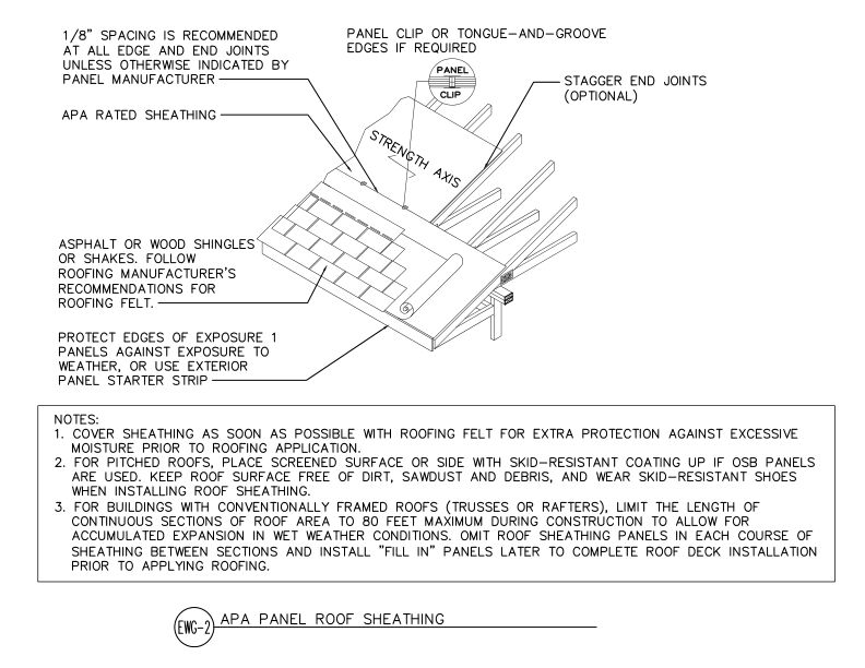
- DT-EWG-2
This detail shows APA Rated sheathing panels installed as roof decking over rafters or trusses with panel clips, asphalt or wood shingles, and proper edge and joint spacing.
Typical Details
- DT-EWG-2
This detail shows APA Rated sheathing panels installed as roof decking over rafters or trusses with panel clips, asphalt or wood shingles, and proper edge and joint spacing.
 Typical Details
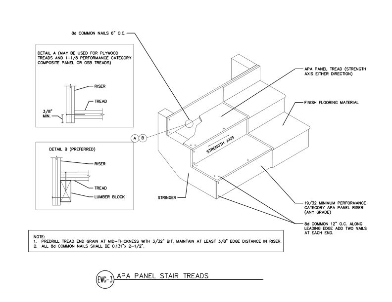
- DT-EWG-3
This detail shows APA panel stair treads and risers installed on stringers in two configurations, using plywood, OSB, or composite panels with 8d common nail fastening.
Typical Details
- DT-EWG-3
This detail shows APA panel stair treads and risers installed on stringers in two configurations, using plywood, OSB, or composite panels with 8d common nail fastening.
 Typical Details
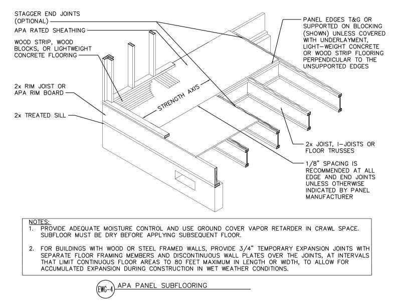
- DT-EWG-4
APA Rated sheathing panels installed as subflooring over 2x joists, I-joists, or floor trusses with tongue-and-groove or blocked edges on a wood-framed floor system.
Typical Details
- DT-EWG-4
APA Rated sheathing panels installed as subflooring over 2x joists, I-joists, or floor trusses with tongue-and-groove or blocked edges on a wood-framed floor system.
 Typical Details
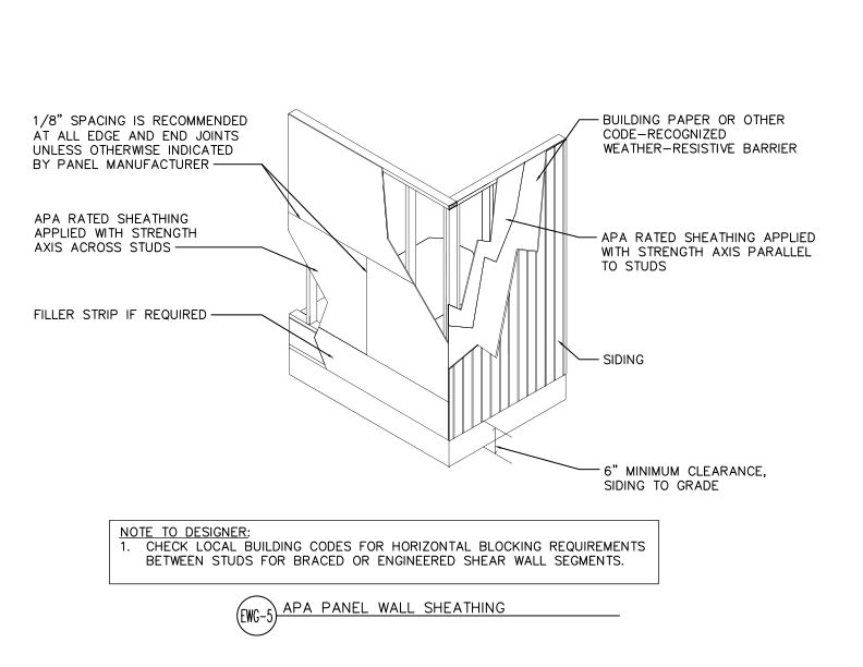
- DT-EWG-5
This detail shows APA Rated wall sheathing applied in two orientations- strength axis across or parallel to studs- with weather-resistive barrier and siding on a wood-framed wall.
Typical Details
- DT-EWG-5
This detail shows APA Rated wall sheathing applied in two orientations- strength axis across or parallel to studs- with weather-resistive barrier and siding on a wood-framed wall.
 Typical Details
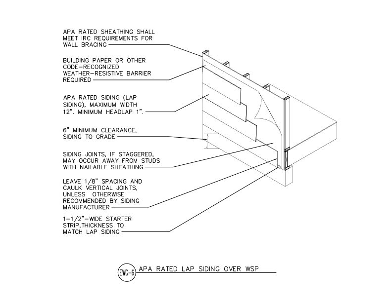
- DT-EWG-6
This detail shows APA Rated lap siding installed over wood structural panel sheathing with a weather-resistive barrier on a wood-framed exterior wall assembly.
Typical Details
- DT-EWG-6
This detail shows APA Rated lap siding installed over wood structural panel sheathing with a weather-resistive barrier on a wood-framed exterior wall assembly.
 Typical Details
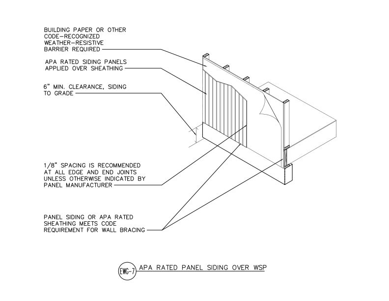
- DT-EWG-7
This detail shows APA Rated siding panels applied over wood structural panel sheathing with a weather-resistive barrier on a wood-framed wall assembly.
Typical Details
- DT-EWG-7
This detail shows APA Rated siding panels applied over wood structural panel sheathing with a weather-resistive barrier on a wood-framed wall assembly.
 Typical Details
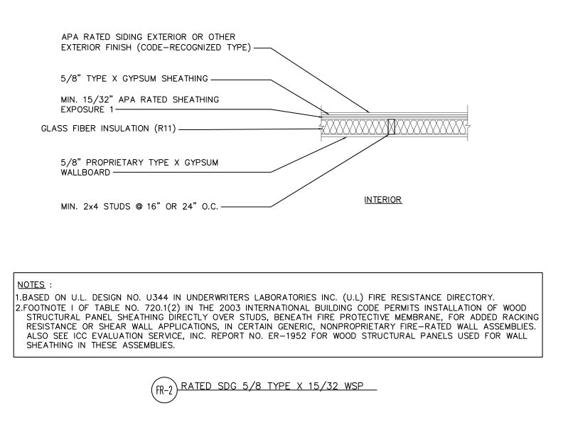
- DT-FR-2
This detail shows a fire-rated wall assembly using wood structural panel sheathing over studs with gypsum wallboard, fire protective membrane, and glass fiber insulation.
Typical Details
- DT-FR-2
This detail shows a fire-rated wall assembly using wood structural panel sheathing over studs with gypsum wallboard, fire protective membrane, and glass fiber insulation.
 Typical Details
- DT-FR-3
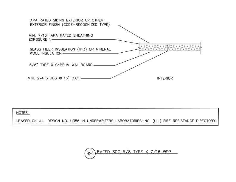
This detail shows fire-rated exterior wall assembly with APA rated siding over sheathing, insulation, 2x4 wood framing at 16" on center and Type X gypsum wallboard interior finish.
Typical Details
- DT-FR-3
This detail shows fire-rated exterior wall assembly with APA rated siding over sheathing, insulation, 2x4 wood framing at 16" on center and Type X gypsum wallboard interior finish.
 Typical Details
- DT-FR-4
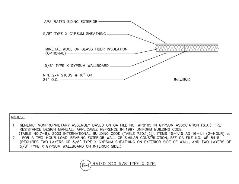
This detail shows a one-hour fire-rated wood-framed wall assembly with Type X gypsum sheathing and wallboard, optional insulation, and APA rated siding exterior finish.
Typical Details
- DT-FR-4
This detail shows a one-hour fire-rated wood-framed wall assembly with Type X gypsum sheathing and wallboard, optional insulation, and APA rated siding exterior finish.
 Typical Details
- DT-EWG-8
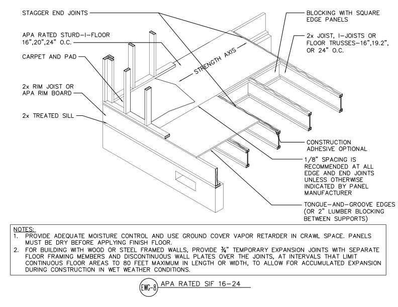
This detail shows APA Rated Sturd-I-Floor panel installation at 16", 20", or 24" o.c. joist spacing with tongue-and-groove edges over a floor framing system.
Typical Details
- DT-EWG-8
This detail shows APA Rated Sturd-I-Floor panel installation at 16", 20", or 24" o.c. joist spacing with tongue-and-groove edges over a floor framing system.
 Typical Details
- DT-EWG-9
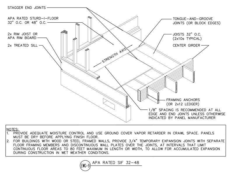
This detail shows APA Rated Sturd-I-Floor panel installation at 32" or 48" o.c. joist spacing with tongue-and-groove joints over a crawl space floor framing system.
Typical Details
- DT-EWG-9
This detail shows APA Rated Sturd-I-Floor panel installation at 32" or 48" o.c. joist spacing with tongue-and-groove joints over a crawl space floor framing system.
 Typical Details
- DT-EWG-10
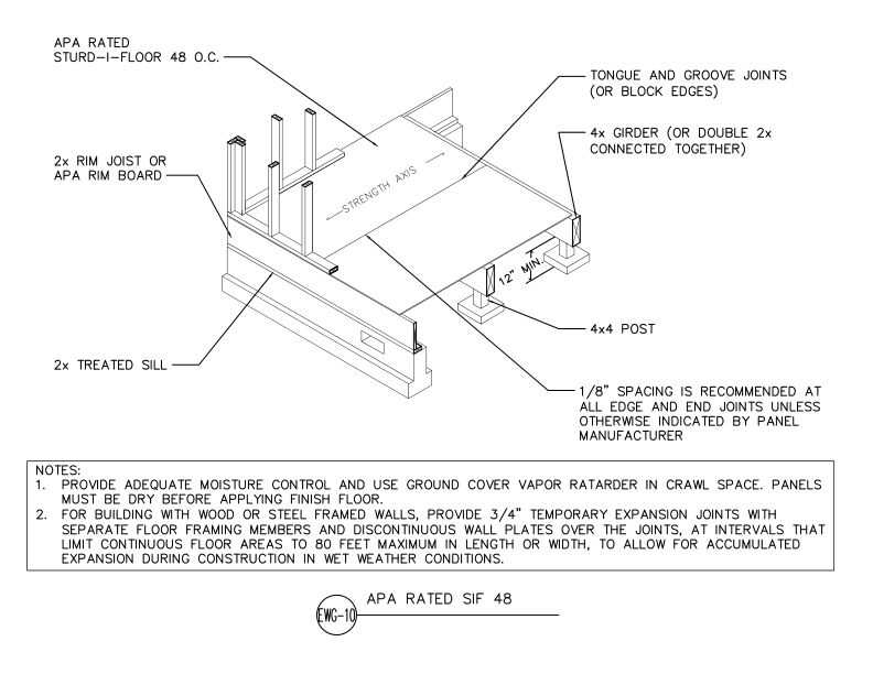
This detail shows APA Rated Sturd-I-Floor 48 o.c. panels installed over a post-and-beam floor framing system with 4x4 posts, 4x girders, and tongue-and-groove panel edges.
Typical Details
- DT-EWG-10
This detail shows APA Rated Sturd-I-Floor 48 o.c. panels installed over a post-and-beam floor framing system with 4x4 posts, 4x girders, and tongue-and-groove panel edges.
 Typical Details
- DT-EWG-12
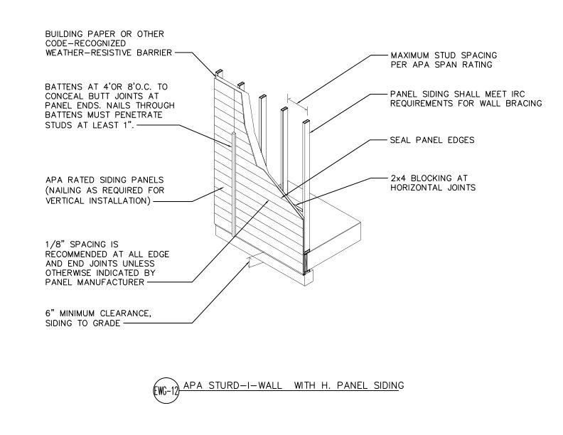
This detail shows APA Rated horizontal panel siding applied directly to wall framing in an APA Sturd-I-Wall system.
Typical Details
- DT-EWG-12
This detail shows APA Rated horizontal panel siding applied directly to wall framing in an APA Sturd-I-Wall system.
 Typical Details
- DT-EWG-13
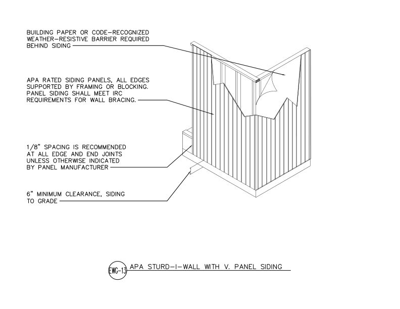
This detail shows APA Rated vertical panel siding applied directly to wall framing in an APA Sturd-I-Wall system with weather-resistive barrier.
Typical Details
- DT-EWG-13
This detail shows APA Rated vertical panel siding applied directly to wall framing in an APA Sturd-I-Wall system with weather-resistive barrier.
 Typical Details
- DT-IJ-1
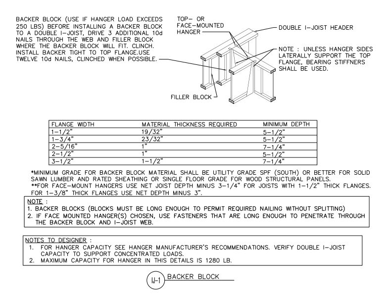
This detail outlines backer block installation for single and double I-joist headers.
Typical Details
- DT-IJ-1
This detail outlines backer block installation for single and double I-joist headers.
 Typical Details
- DT-GB-1
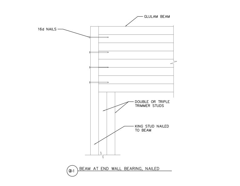
This detail shows glulam beam bearing at an end wall. The beam is supported by trimmer studs and secured to the king stud with 16d nails.
Typical Details
- DT-GB-1
This detail shows glulam beam bearing at an end wall. The beam is supported by trimmer studs and secured to the king stud with 16d nails.
 Typical Details
- DT-GB-2
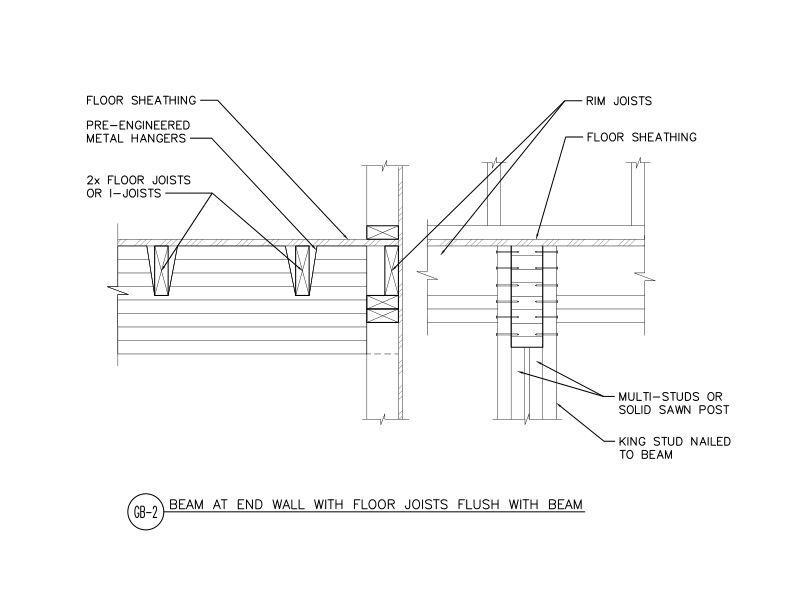
This detail shows a glulam beam connection to an end wall with flush floor joists or I-joists connected to the beam.
Typical Details
- DT-GB-2
This detail shows a glulam beam connection to an end wall with flush floor joists or I-joists connected to the beam.
 Typical Details
- DT-GB-3
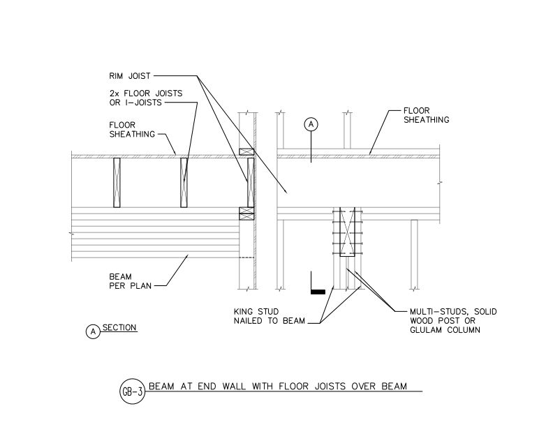
This detail shows a glulam beam connection to an end wall with I-joists bearing on the beam.
Typical Details
- DT-GB-3
This detail shows a glulam beam connection to an end wall with I-joists bearing on the beam.
 Typical Details
- DT-GB-6
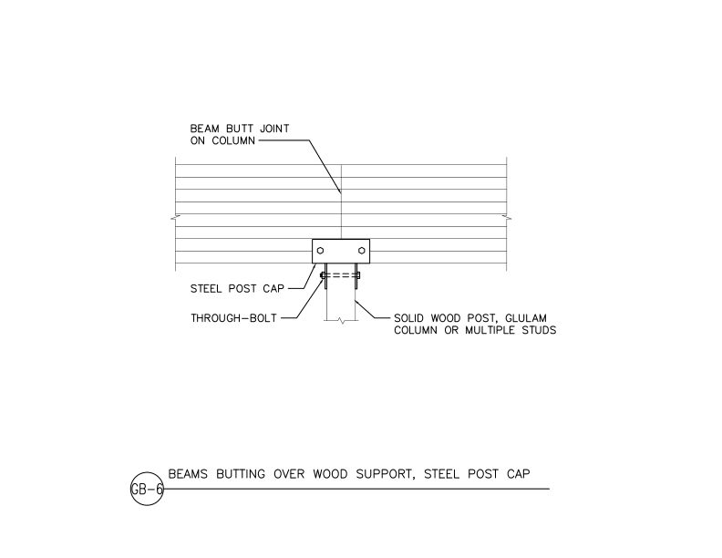
This detail shows two glulam beams butting over a wood support, with the beams connected to the support using a steel post cap and through-bolts.
Typical Details
- DT-GB-6
This detail shows two glulam beams butting over a wood support, with the beams connected to the support using a steel post cap and through-bolts.
 Typical Details
- DT-GB-8
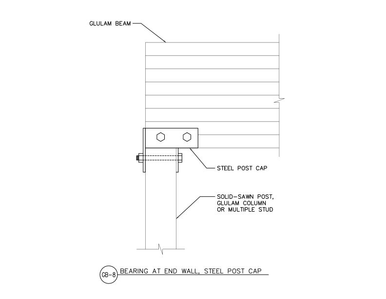
This detail shows connection of glulam beam bearing on solid-sawn post or glulam column using steel post cap at end wall condition.
Typical Details
- DT-GB-8
This detail shows connection of glulam beam bearing on solid-sawn post or glulam column using steel post cap at end wall condition.
 Typical Details
- DT-GB-9
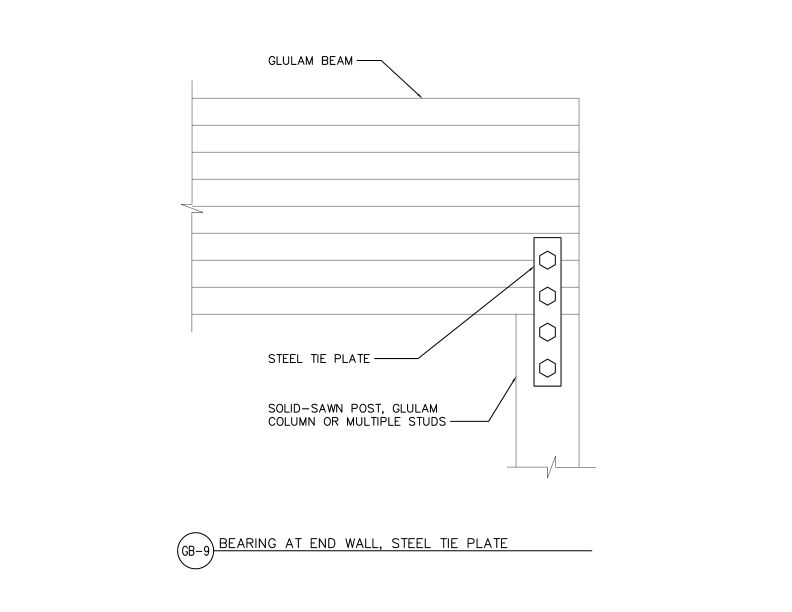
This detail shows a steel tie plate connection for a glulam beam bearing on a wood support at an end condition.
Typical Details
- DT-GB-9
This detail shows a steel tie plate connection for a glulam beam bearing on a wood support at an end condition.
 Typical Details
- DT-SIP-1
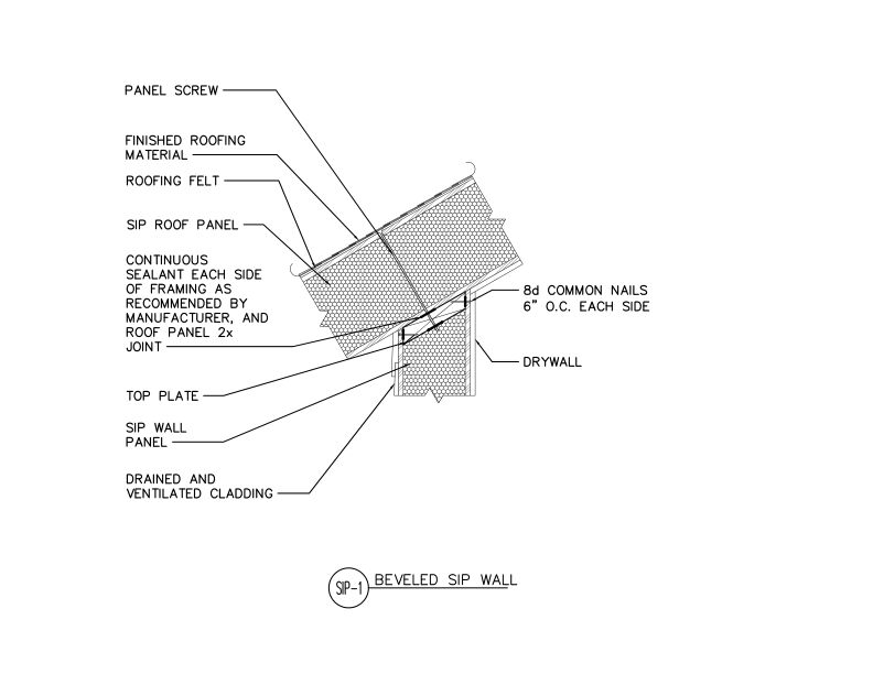
This detail shows a SIP wall beveled to support a sloped SIP roof that are connected together with panel screws and nails. It also shows sealant, roofing material and cladding.
Typical Details
- DT-SIP-1
This detail shows a SIP wall beveled to support a sloped SIP roof that are connected together with panel screws and nails. It also shows sealant, roofing material and cladding.
 Typical Details
- DT-BB-2
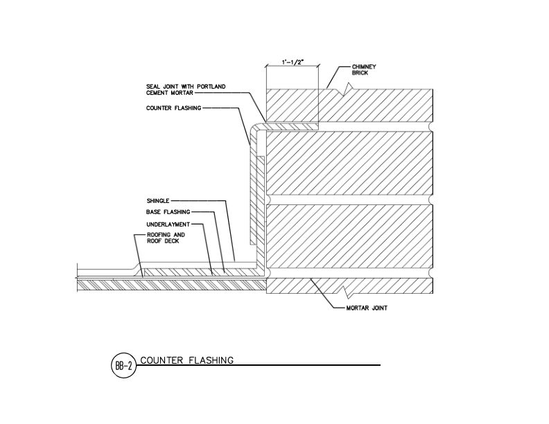
This detail shows chimney counter flashing detail of base flashing over shingle underlayment and roof deck, with counter flashing embedded in brick mortar joint.
Typical Details
- DT-BB-2
This detail shows chimney counter flashing detail of base flashing over shingle underlayment and roof deck, with counter flashing embedded in brick mortar joint.
 Typical Details
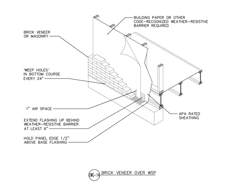
- DT-EWG-14
This detail shows brick veneer or masonry cladding installed over APA Rated wood structural panel sheathing.
Typical Details
- DT-EWG-14
This detail shows brick veneer or masonry cladding installed over APA Rated wood structural panel sheathing.
 Typical Details
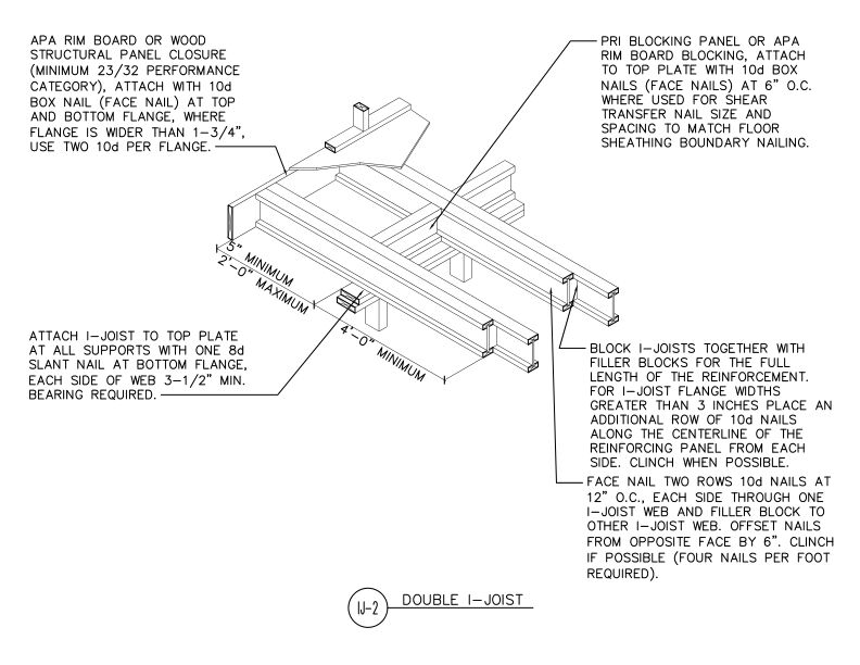
- DT-IJ-2
This detail shows cantilevered double I-joists supporting a vertical building offset and specifies connections to the top plate, blocking panels, and Rim Board or APA WSP closure.
Typical Details
- DT-IJ-2
This detail shows cantilevered double I-joists supporting a vertical building offset and specifies connections to the top plate, blocking panels, and Rim Board or APA WSP closure.
 Typical Details
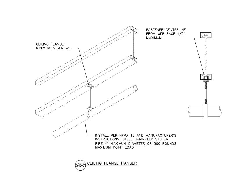
- DT-SPR-2
This detail shows ceiling flange hanger installation for supporting steel sprinkler system pipes from engineered wood ceiling joists.
Typical Details
- DT-SPR-2
This detail shows ceiling flange hanger installation for supporting steel sprinkler system pipes from engineered wood ceiling joists.
 Typical Details
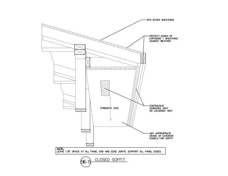
- DT-EWG-15
This detail shows a closed soffit assembly using APA rated roof sheathing and exterior panels for the closed soffit with continuous screened or louvered venting.
Typical Details
- DT-EWG-15
This detail shows a closed soffit assembly using APA rated roof sheathing and exterior panels for the closed soffit with continuous screened or louvered venting.
 Typical Details
- DT-SPR-3
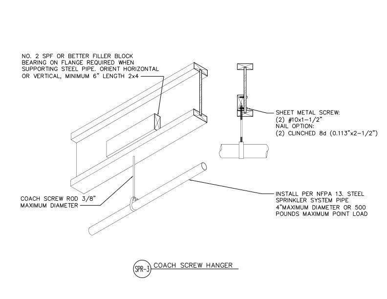
This detail shows a coach screw hanger assembly for supporting steel sprinkler pipe from wood framing using filler blocks and sheet metal screws or nails.
Typical Details
- DT-SPR-3
This detail shows a coach screw hanger assembly for supporting steel sprinkler pipe from wood framing using filler blocks and sheet metal screws or nails.
 Typical Details
- DT-BB-1
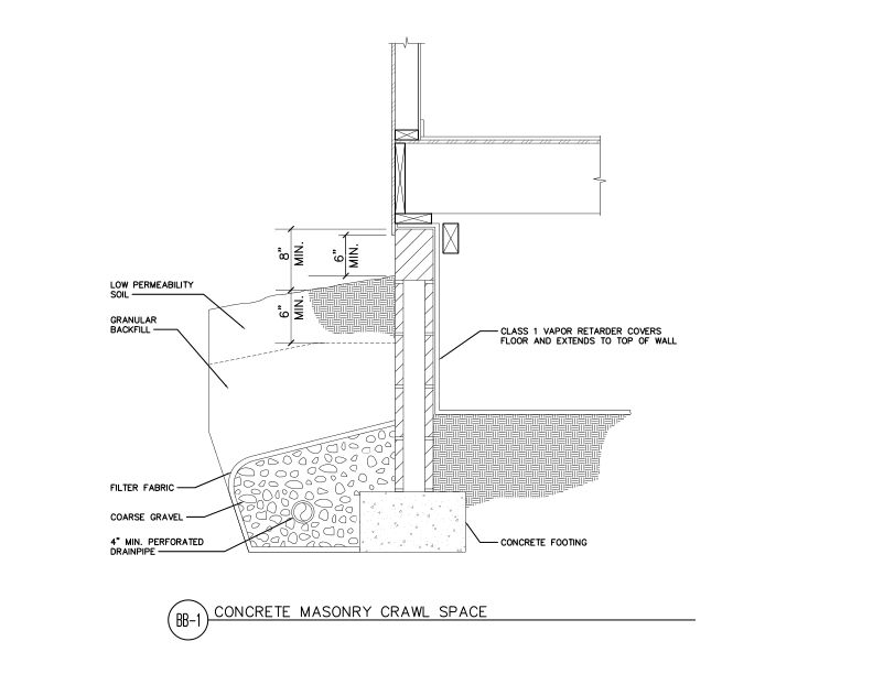
This detail shows concrete masonry crawl space foundation.
Typical Details
- DT-BB-1
This detail shows concrete masonry crawl space foundation.
 Typical Details
- DT-GB-10
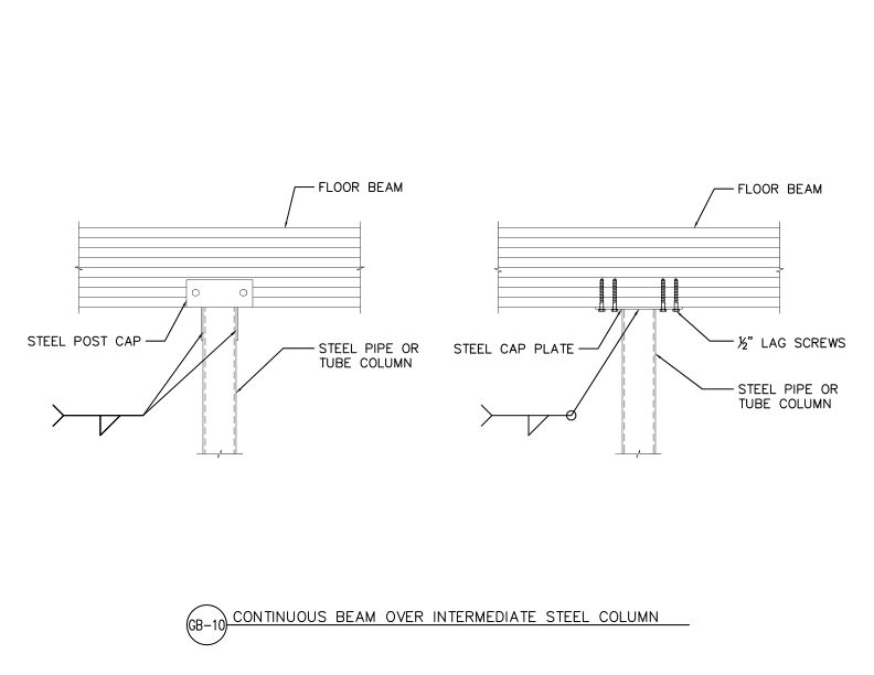
This detail shows two options for connecting a continuous glulam floor beam to an intermediate steel column using either a steel post cap or steel cap plate.
Typical Details
- DT-GB-10
This detail shows two options for connecting a continuous glulam floor beam to an intermediate steel column using either a steel post cap or steel cap plate.
 Typical Details
- DT-GB-11
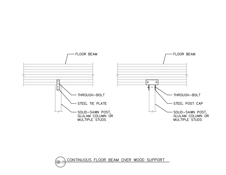
This detail shows two connection options for a continuous glulam floor beam bearing on a wood support.
Typical Details
- DT-GB-11
This detail shows two connection options for a continuous glulam floor beam bearing on a wood support.
 Typical Details
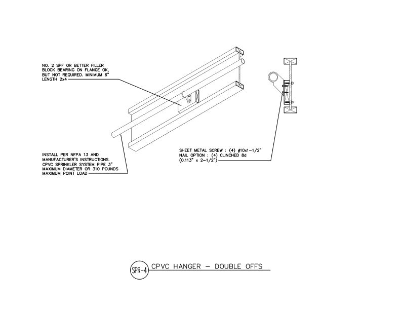
- DT-SPR-4
This detail shows double offset CPVC sprinkler pipe hanger assembly using 2x4 blocking with sheet metal screws or nails, supporting 3" maximum diameter pipe per NFPA 13.
Typical Details
- DT-SPR-4
This detail shows double offset CPVC sprinkler pipe hanger assembly using 2x4 blocking with sheet metal screws or nails, supporting 3" maximum diameter pipe per NFPA 13.
 Typical Details
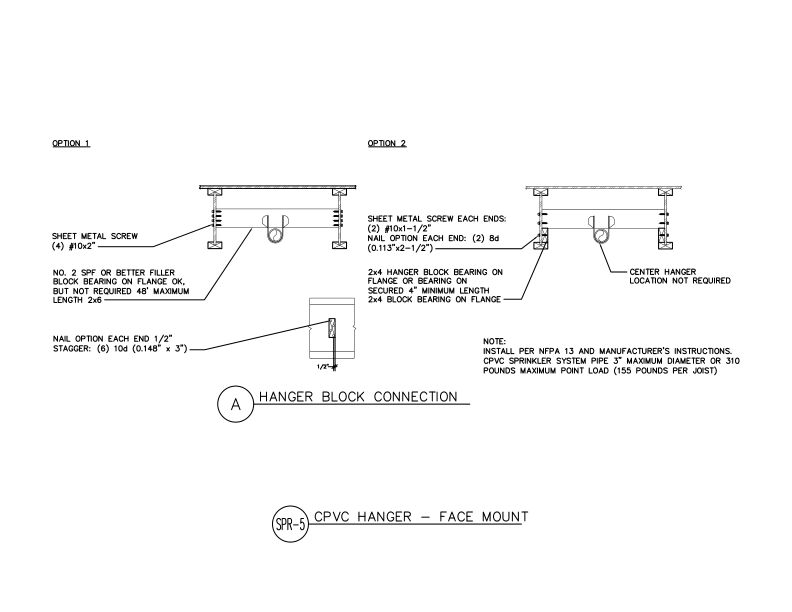
- DT-SPR-5
This detail shows two installation options for face-mounting CPVC sprinkler pipe hangers to wood blocking using either sheet metal screws or nail-and-block combinations.
Typical Details
- DT-SPR-5
This detail shows two installation options for face-mounting CPVC sprinkler pipe hangers to wood blocking using either sheet metal screws or nail-and-block combinations.
 Typical Details
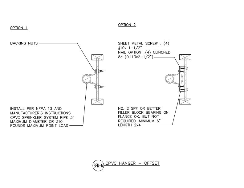
- DT-SPR-6
This detail shows offset hanger installation for CPVC sprinkler system pipes showing two attachment options using backing nuts or sheet metal screws with lumber blocking.
Typical Details
- DT-SPR-6
This detail shows offset hanger installation for CPVC sprinkler system pipes showing two attachment options using backing nuts or sheet metal screws with lumber blocking.
 Typical Details
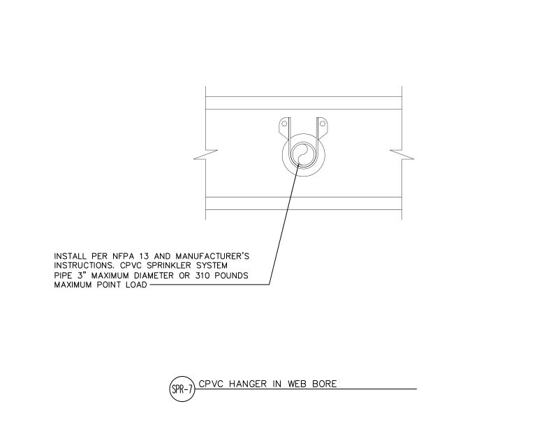
- DT-SPR-7
This detail shows proper installation of a CPVC sprinkler system pipe hanger through an I-joist web bore, with maximum diameter and load requirements per NFPA 13.
Typical Details
- DT-SPR-7
This detail shows proper installation of a CPVC sprinkler system pipe hanger through an I-joist web bore, with maximum diameter and load requirements per NFPA 13.
 Typical Details
- DT-SPR-8
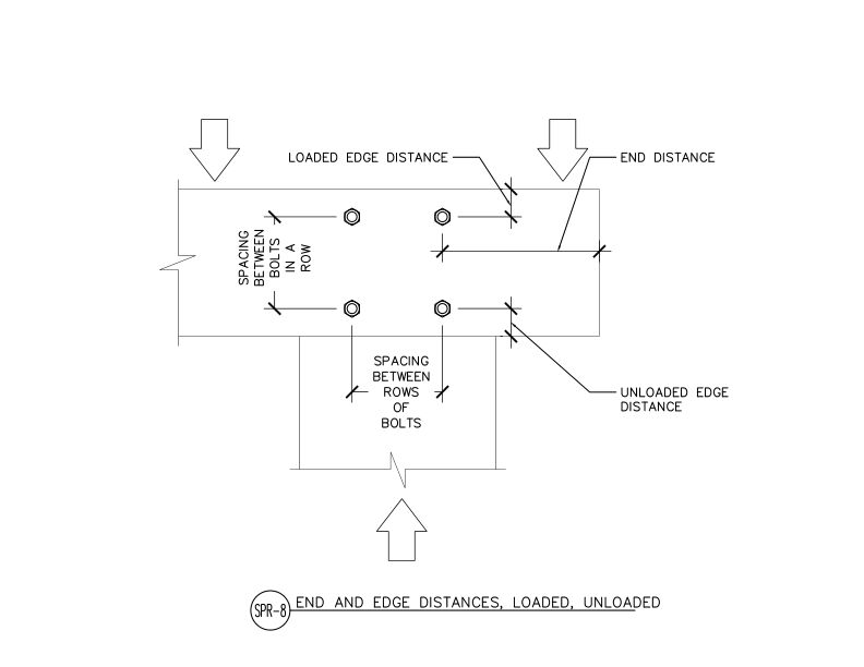
This detail shows proper bolt spacing requirements including loaded edge distance, unloaded edge distance, end distance, and spacing between rows of bolts.
Typical Details
- DT-SPR-8
This detail shows proper bolt spacing requirements including loaded edge distance, unloaded edge distance, end distance, and spacing between rows of bolts.
 Typical Details
- DT-EWG-16
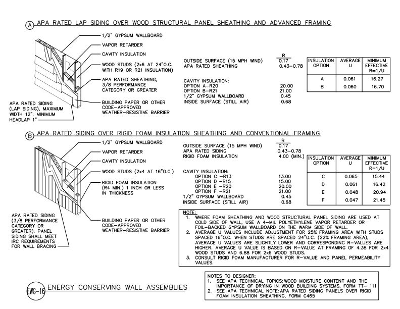
This detail shows two energy-conserving exterior wall assemblies.
Typical Details
- DT-EWG-16
This detail shows two energy-conserving exterior wall assemblies.
 Typical Details
- DT-RH-1
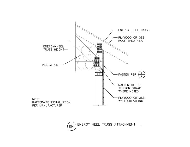
This detail shows raised heel energy truss attachment to an exterior wall for additional attic insulation space.
Typical Details
- DT-RH-1
This detail shows raised heel energy truss attachment to an exterior wall for additional attic insulation space.
 Typical Details
- DT-BB-3
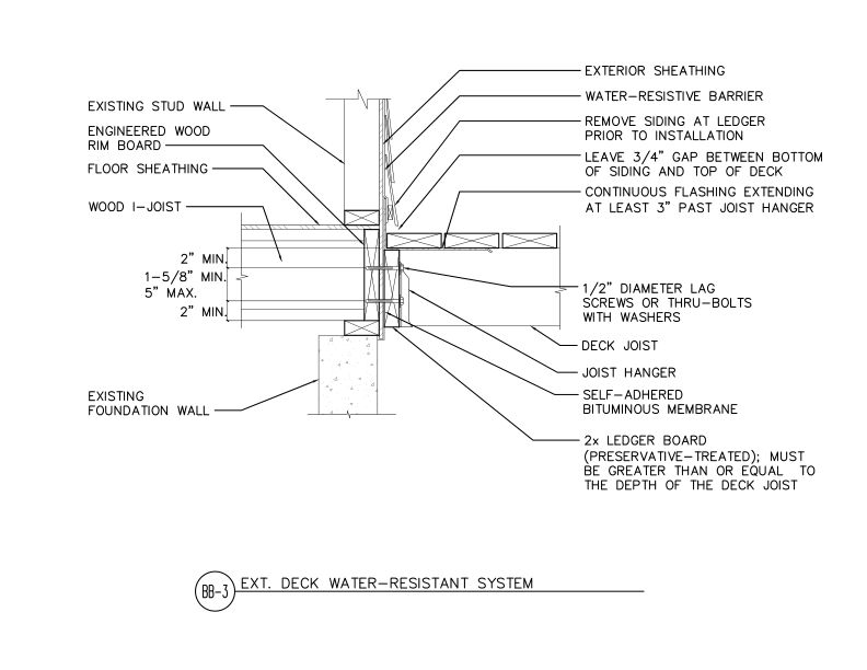
This detail shows exterior deck ledger connection to wood I-joist floor system of water-resistant flashing.
Typical Details
- DT-BB-3
This detail shows exterior deck ledger connection to wood I-joist floor system of water-resistant flashing.
 Typical Details
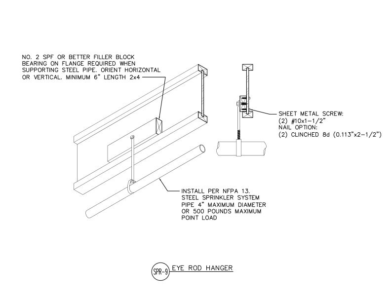
- DT-SPR-9
This detail shows eye rod hanger for supporting steel sprinkler pipes from wood framing using filler blocks and sheet metal screws or nails per NFPA 13 requirements.
Typical Details
- DT-SPR-9
This detail shows eye rod hanger for supporting steel sprinkler pipes from wood framing using filler blocks and sheet metal screws or nails per NFPA 13 requirements.
 Typical Details
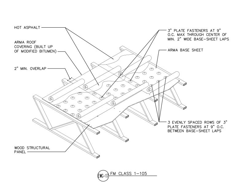
- DT-EWG-17
This detail shows an FM Class 1-105 rated flat roof assembly using wood structural panels over open-web trusses.
Typical Details
- DT-EWG-17
This detail shows an FM Class 1-105 rated flat roof assembly using wood structural panels over open-web trusses.
 Typical Details
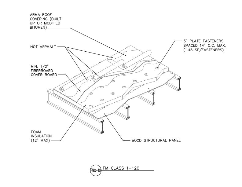
- DT-EWG-18
This detail shows an FM Class 1-120 rated flat roof assembly using wood structural panels over steel joists.
Typical Details
- DT-EWG-18
This detail shows an FM Class 1-120 rated flat roof assembly using wood structural panels over steel joists.
 Typical Details
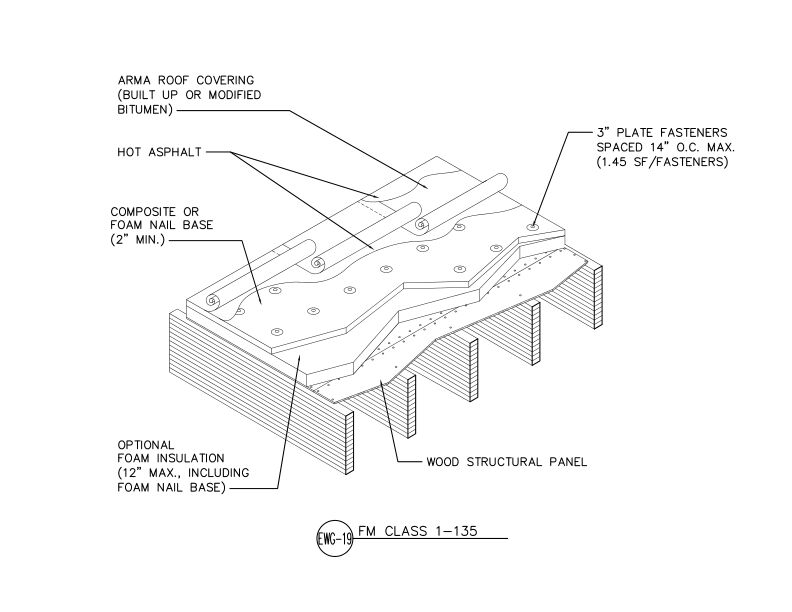
- DT-EWG-19
This detail shows an FM Class 1-135 rated flat roof assembly using wood structural panels.
Typical Details
- DT-EWG-19
This detail shows an FM Class 1-135 rated flat roof assembly using wood structural panels.
 Typical Details
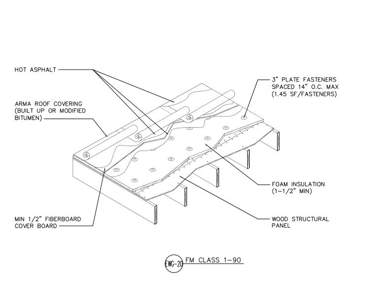
- DT-EWG-20
This detail shows an FM Class 1-90 rated flat roof assembly using wood structural panels with foam insulation, fiberboard cover board, and built-up or modified bitumen roofing.
Typical Details
- DT-EWG-20
This detail shows an FM Class 1-90 rated flat roof assembly using wood structural panels with foam insulation, fiberboard cover board, and built-up or modified bitumen roofing.
 Typical Details
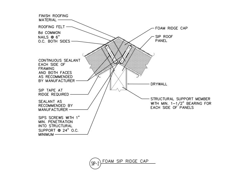
- DT-SIP-2
This detail shows roof SIPs sloped up to form a ridge and connections of the SIPs to framing members with panel screws, while also showing tape, sealant, and roofing materials.
Typical Details
- DT-SIP-2
This detail shows roof SIPs sloped up to form a ridge and connections of the SIPs to framing members with panel screws, while also showing tape, sealant, and roofing materials.
 Typical Details
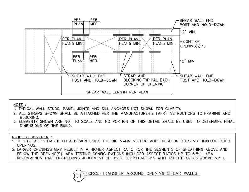
- DT-FTO-1
This detail shows the layout of a force transfer around opening shear wall.
Typical Details
- DT-FTO-1
This detail shows the layout of a force transfer around opening shear wall.
 Typical Details
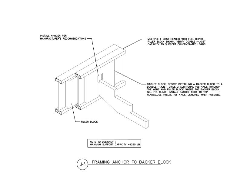
- DT-IJ-3
This detail shows installation of backer and filler blocks for a double I-joist header supporting a stair stringer that is attached with a framing anchor.
Typical Details
- DT-IJ-3
This detail shows installation of backer and filler blocks for a double I-joist header supporting a stair stringer that is attached with a framing anchor.
 Typical Details
- DT-GH-1
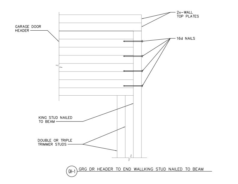
This detail shows a connection of a garage door header at and end wall where a glulam beam is connected to a king stud with nails.
Typical Details
- DT-GH-1
This detail shows a connection of a garage door header at and end wall where a glulam beam is connected to a king stud with nails.
 Typical Details
- DT-GH-2
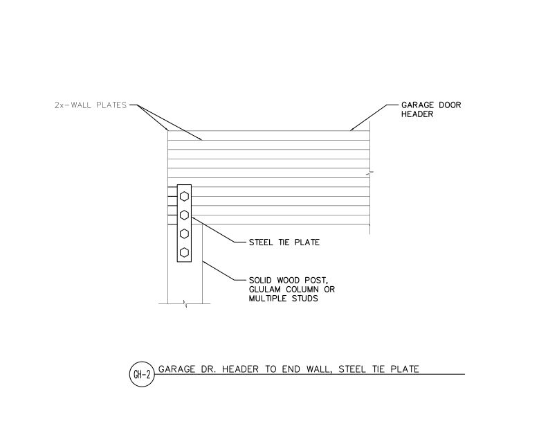
This detail shows a connection of a garage door header and an end wall using a steel plate fastened to a solid wood post, glulam column or studs.
Typical Details
- DT-GH-2
This detail shows a connection of a garage door header and an end wall using a steel plate fastened to a solid wood post, glulam column or studs.
 Typical Details
- DT-IJ-4
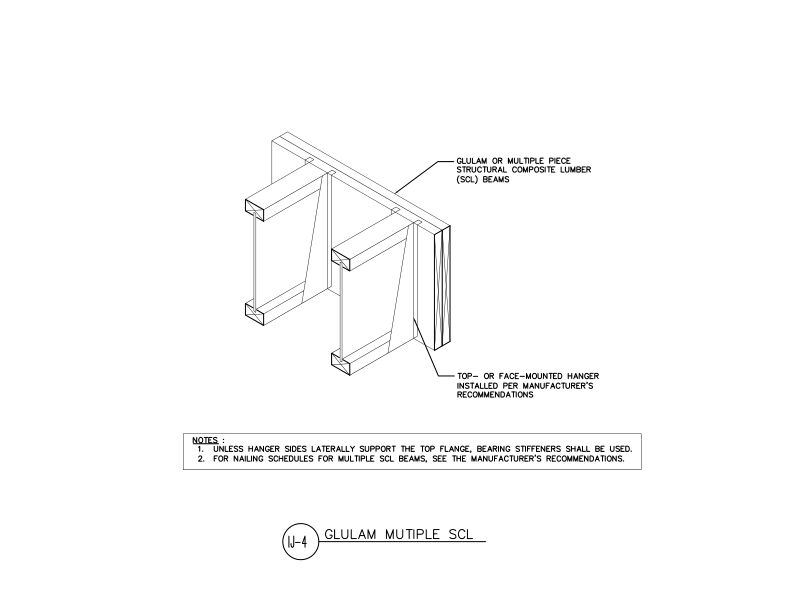
This detail shows I-Joists with top mount hangers supported by a multi-ply structural composite lumber (SCL) beam. This detail is similar for a glulam beam with face mount hangers.
Typical Details
- DT-IJ-4
This detail shows I-Joists with top mount hangers supported by a multi-ply structural composite lumber (SCL) beam. This detail is similar for a glulam beam with face mount hangers.
 Typical Details
- DT-SIP-3
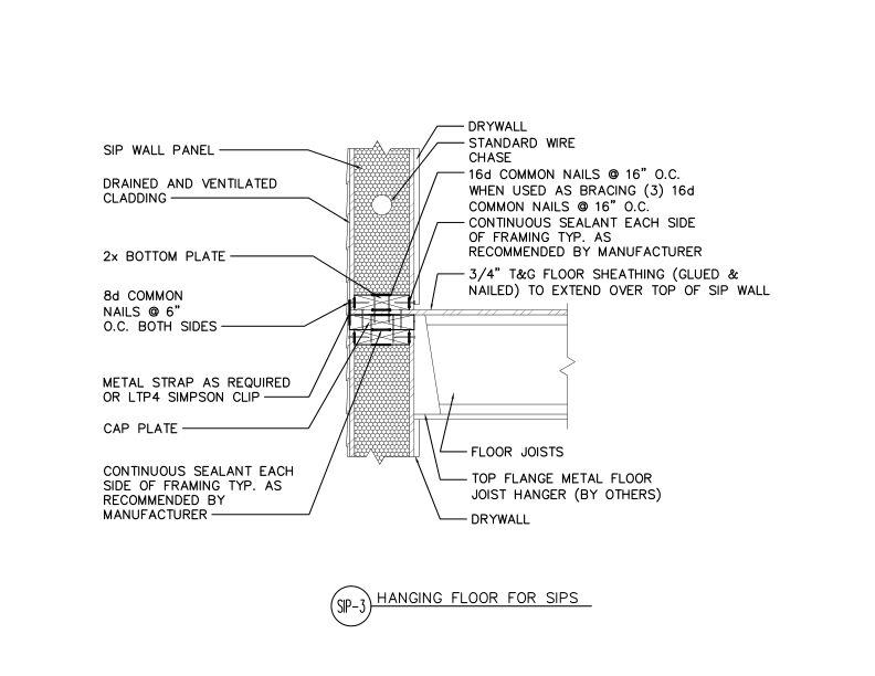
This detail shows how to attach a floor system in between the top and bottom of two SIP walls by hanging the joists at the top of a SIP with top mount hangers and a cap plate.
Typical Details
- DT-SIP-3
This detail shows how to attach a floor system in between the top and bottom of two SIP walls by hanging the joists at the top of a SIP with top mount hangers and a cap plate.
 Typical Details
- DT-EWG-21
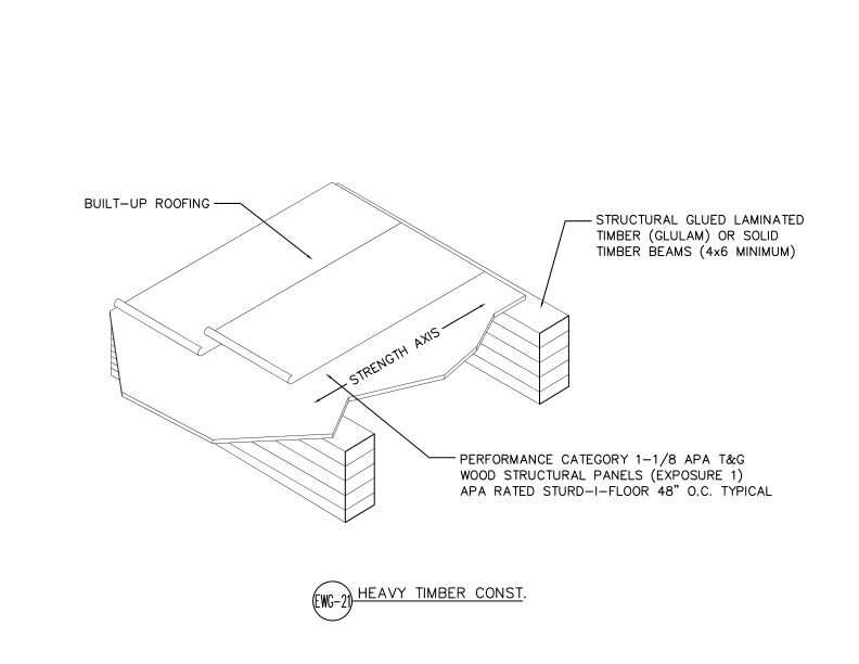
This detail shows a heavy timber roof construction assembly using APA Rated Sturd-I-Floor T&G panels over structural glulam or solid timber beams with built-up roofing.
Typical Details
- DT-EWG-21
This detail shows a heavy timber roof construction assembly using APA Rated Sturd-I-Floor T&G panels over structural glulam or solid timber beams with built-up roofing.
 Typical Details
- DT-EWG-22
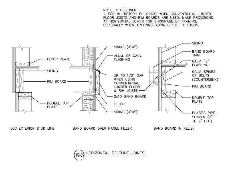
This detail shows three horizontal beltline joint configurations for APA panel siding at floor lines in multistory construction.
Typical Details
- DT-EWG-22
This detail shows three horizontal beltline joint configurations for APA panel siding at floor lines in multistory construction.
 Typical Details
- DT-EWG-23
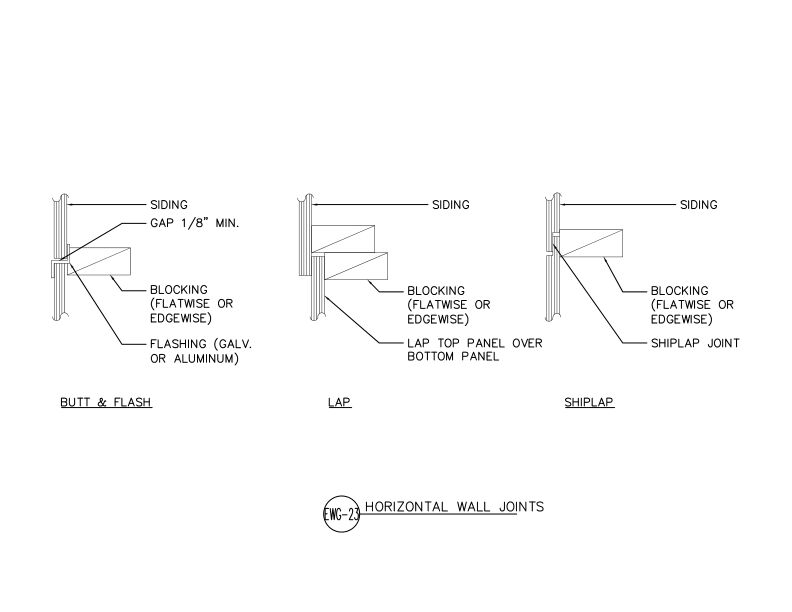
This detail shows three horizontal joint configurations for APA panel siding — butt and flash, lap, and shiplap — each with blocking flatwise or edgewise at the joint location.
Typical Details
- DT-EWG-23
This detail shows three horizontal joint configurations for APA panel siding — butt and flash, lap, and shiplap — each with blocking flatwise or edgewise at the joint location.
 Typical Details
- DT-IJ-5
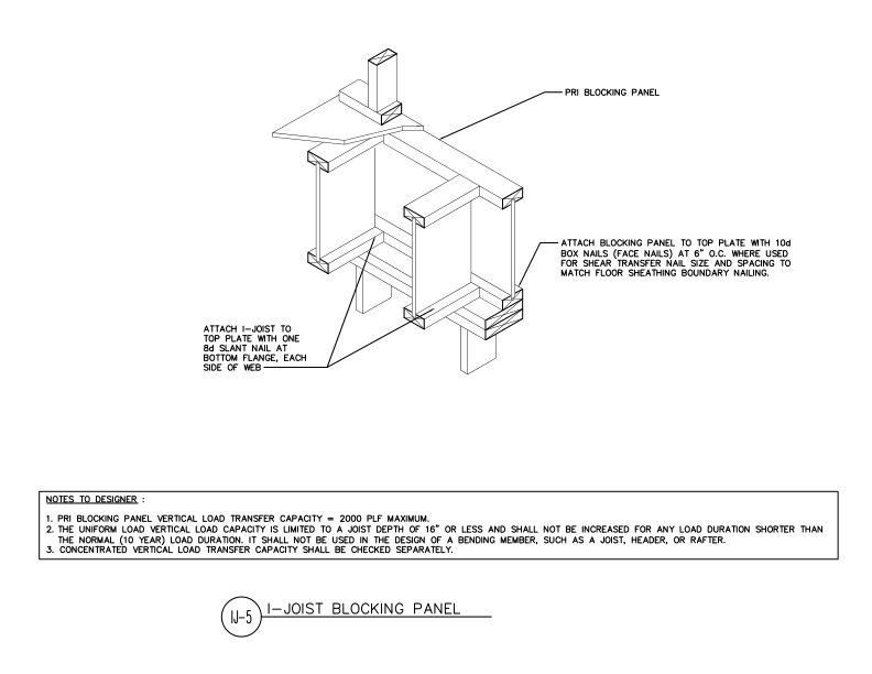
This detail shows the installation of PRI blocking panels between I-joists, attached to top plate with face nails for shear transfer at floor sheathing boundaries.
Typical Details
- DT-IJ-5
This detail shows the installation of PRI blocking panels between I-joists, attached to top plate with face nails for shear transfer at floor sheathing boundaries.
 Typical Details
- DT-IJ-6
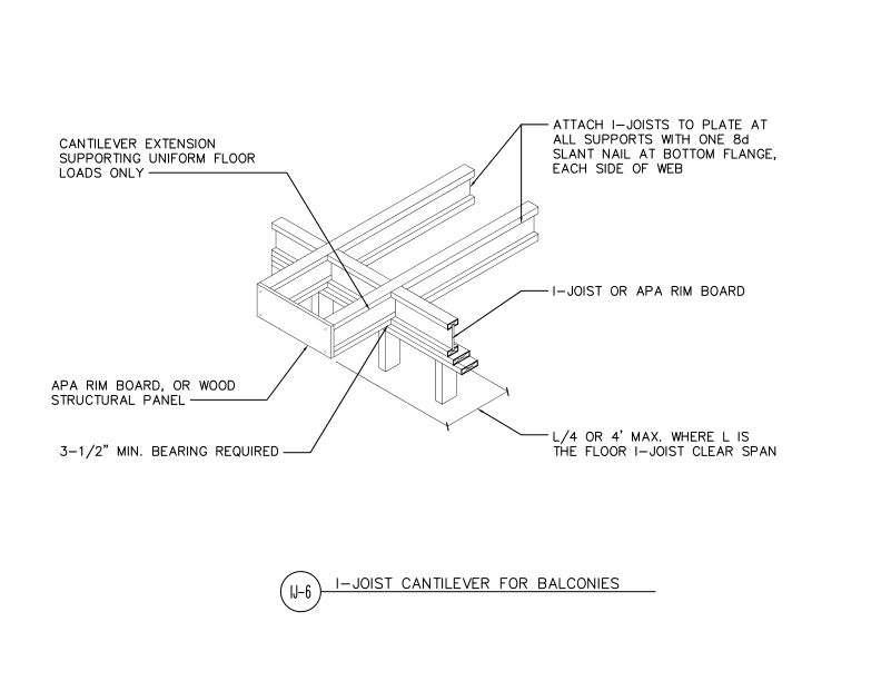
This detail outlines proper construction methods for cantilevered I-joist floor extensions, such as balconies.
Typical Details
- DT-IJ-6
This detail outlines proper construction methods for cantilevered I-joist floor extensions, such as balconies.
 Typical Details
- DT-FPF-4
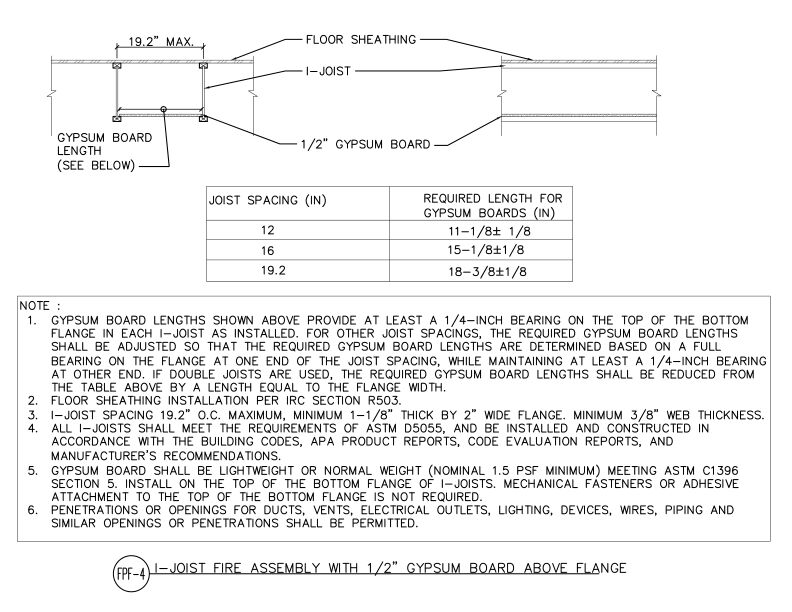
This detail shows an I-joist floor assembly with 1/2" gypsum board placed above the bottom flange for fire protection per IRC Section R503.
Typical Details
- DT-FPF-4
This detail shows an I-joist floor assembly with 1/2" gypsum board placed above the bottom flange for fire protection per IRC Section R503.
 Typical Details
- DT-FPF-5
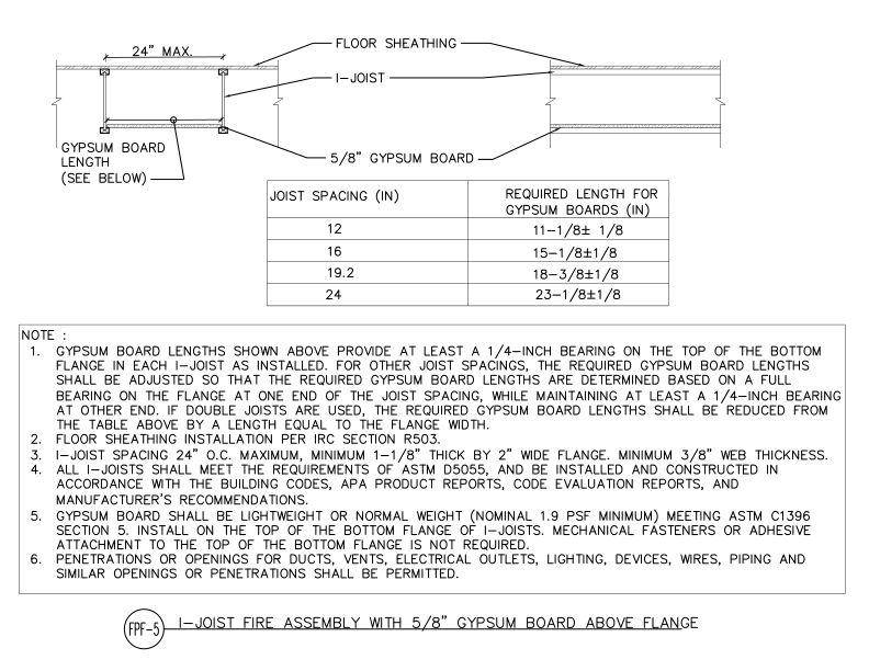
This detail shows an I-joist floor assembly with 5/8" gypsum board placed above the bottom flange for fire protection per IRC Section R503.
Typical Details
- DT-FPF-5
This detail shows an I-joist floor assembly with 5/8" gypsum board placed above the bottom flange for fire protection per IRC Section R503.
 Typical Details
- DT-FPF-2
This detail shows 1/2" gypsum board fastened to the bottom flange of an I-joist floor assembly for fire protection per IRC Section R702.3.1.
Typical Details
- DT-FPF-2
This detail shows 1/2" gypsum board fastened to the bottom flange of an I-joist floor assembly for fire protection per IRC Section R702.3.1.
 Typical Details
- DT-FPF-1
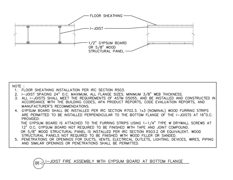
This detail shows 1/2" gypsum board or 5/8" wood structural panel installed at the bottom flange of an I-joist floor assembly for fire protection per IRC Section R702.3.
Typical Details
- DT-FPF-1
This detail shows 1/2" gypsum board or 5/8" wood structural panel installed at the bottom flange of an I-joist floor assembly for fire protection per IRC Section R702.3.
 Typical Details
- DT-FPF-3
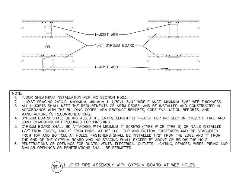
This detail shows 1/2" gypsum board installed at I-joist web holes for fire protection, shown in two configurations per IRC Section R702.3.1.
Typical Details
- DT-FPF-3
This detail shows 1/2" gypsum board installed at I-joist web holes for fire protection, shown in two configurations per IRC Section R702.3.1.
 Typical Details
- DT-FPF-7
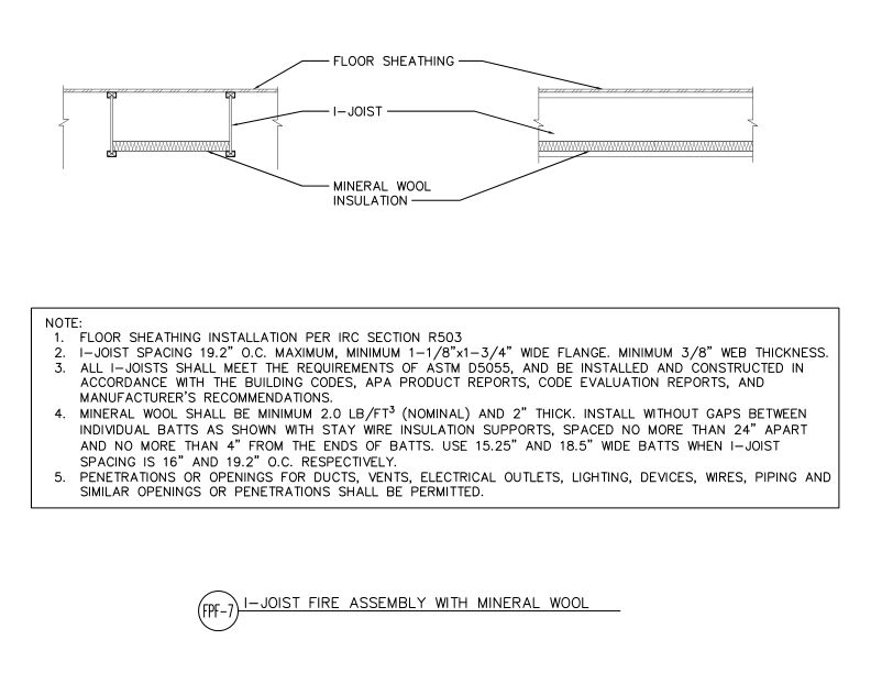
This detail shows an I-joist floor assembly with mineral wool insulation for fire protection per IRC Section R503.
Typical Details
- DT-FPF-7
This detail shows an I-joist floor assembly with mineral wool insulation for fire protection per IRC Section R503.
 Typical Details
- DT-FPF-6
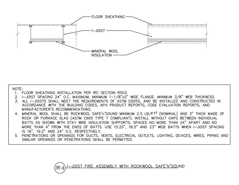
This detail shows an I-joist floor assembly with Rockwool Safe'n'Sound mineral wool insulation for fire protection per IRC Section R503.
Typical Details
- DT-FPF-6
This detail shows an I-joist floor assembly with Rockwool Safe'n'Sound mineral wool insulation for fire protection per IRC Section R503.
 Typical Details
- DT-GB-12
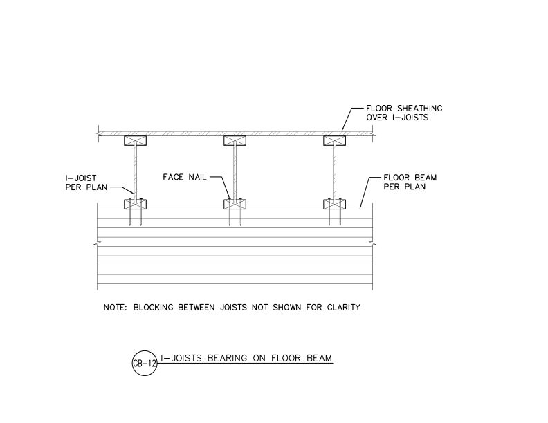
This detail shows I-joists bearing on a glulam floor beam with face nail connections and blocking not shown for clarity.
Typical Details
- DT-GB-12
This detail shows I-joists bearing on a glulam floor beam with face nail connections and blocking not shown for clarity.
 Typical Details
- DT-EWG-24
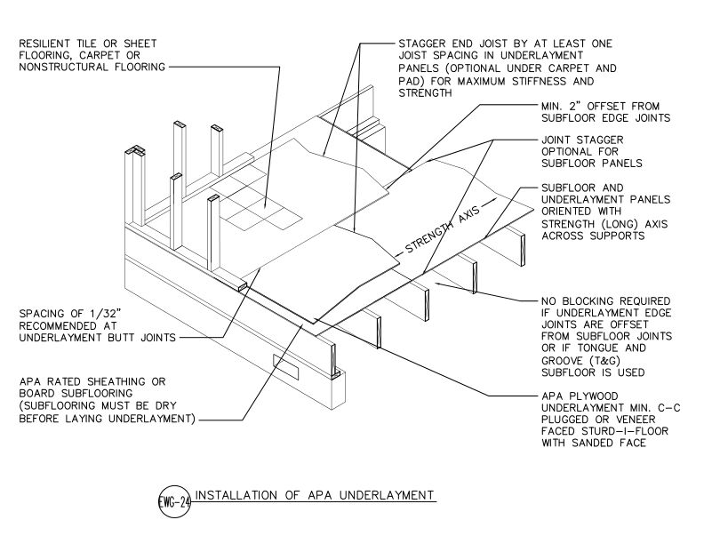
This detail shows APA plywood underlayment installation over APA Rated sheathing subfloor.
Typical Details
- DT-EWG-24
This detail shows APA plywood underlayment installation over APA Rated sheathing subfloor.
 Typical Details
- DT-AF-2
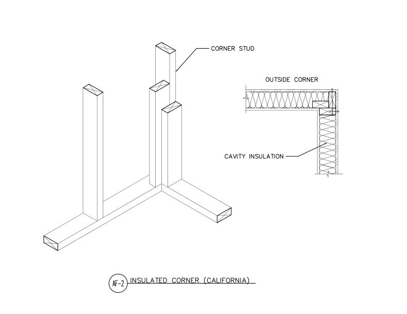
This detail shows an insulated three-stud outside corner (California corner) framing assembly.
Typical Details
- DT-AF-2
This detail shows an insulated three-stud outside corner (California corner) framing assembly.
 Typical Details
- DT-AF-3
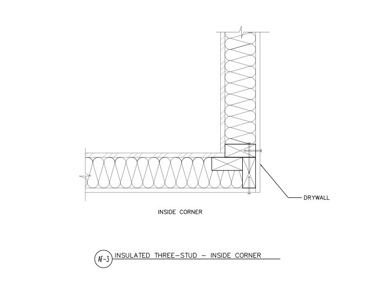
This detail shows an insulated three-stud inside corner framing assembly.
Typical Details
- DT-AF-3
This detail shows an insulated three-stud inside corner framing assembly.
 Typical Details
- DT-AF-4
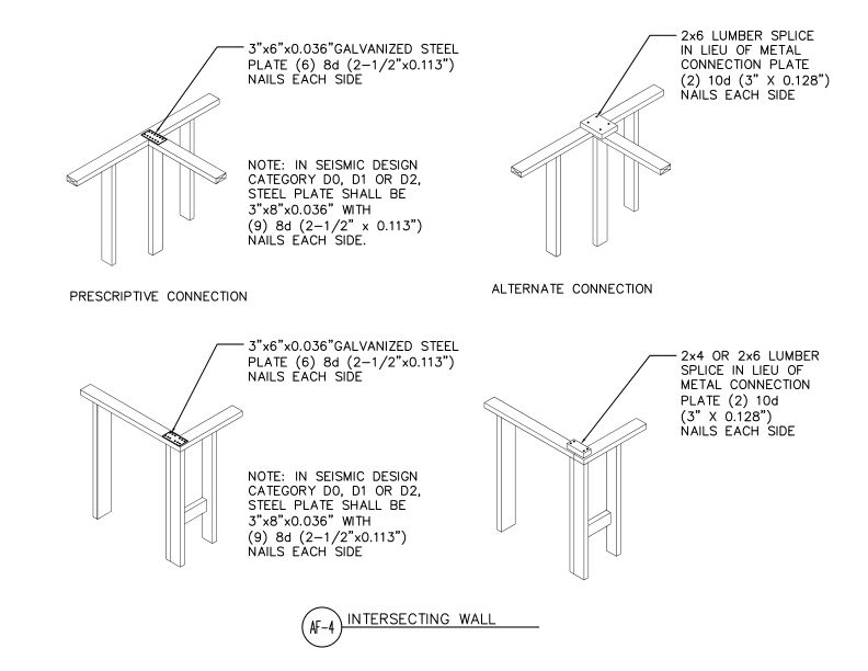
This detail shows connections of intersecting single 2x top plates with steel plates and alternate lumber splice connections.
Typical Details
- DT-AF-4
This detail shows connections of intersecting single 2x top plates with steel plates and alternate lumber splice connections.
 Typical Details
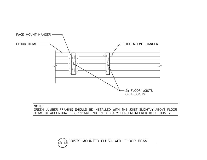
- DT-GB-13
This detail shows two floor joist flush connections options: one face mounted hanger and one top mounted hanger.
Typical Details
- DT-GB-13
This detail shows two floor joist flush connections options: one face mounted hanger and one top mounted hanger.
 Typical Details
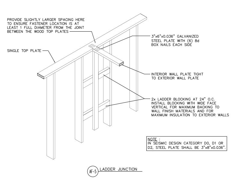
- DT-AF-5
This detail shows an advanced framed wall junction with single top plates and 2x ladder blocking spaced vertically at 24” O.C. for an interior wall to exterior wall connection.
Typical Details
- DT-AF-5
This detail shows an advanced framed wall junction with single top plates and 2x ladder blocking spaced vertically at 24” O.C. for an interior wall to exterior wall connection.
 Typical Details
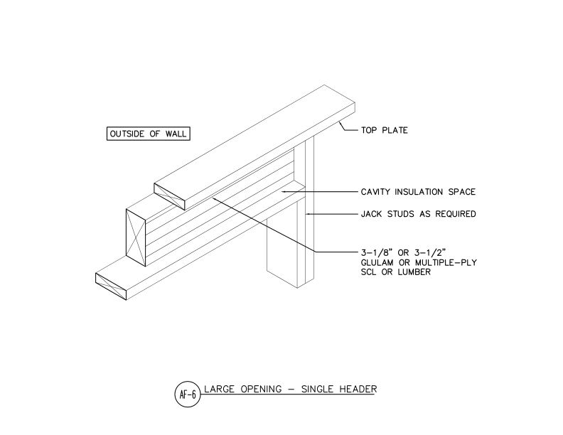
- DT-AF-6
This detail shows the use of a single header with a width less than the wall to create more space for insulation.
Typical Details
- DT-AF-6
This detail shows the use of a single header with a width less than the wall to create more space for insulation.
 Typical Details
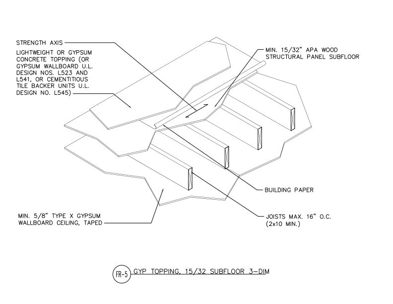
- DT-FR-5
This detail shows three-dimensional floor assembly of APA wood structural panel subflooring with gypsum concrete topping over joists and Type X gypsum wallboard ceiling below.
Typical Details
- DT-FR-5
This detail shows three-dimensional floor assembly of APA wood structural panel subflooring with gypsum concrete topping over joists and Type X gypsum wallboard ceiling below.
 Typical Details
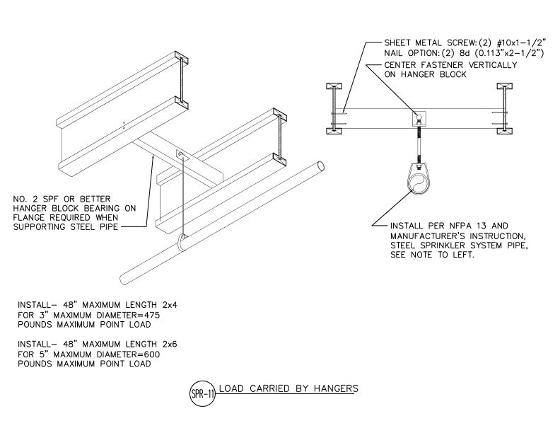
- DT-SPR-11
Installation detail for supporting steel sprinkler pipes from structural framing using hanger blocks with fastening specifications for different pipe sizes and loads.
Typical Details
- DT-SPR-11
Installation detail for supporting steel sprinkler pipes from structural framing using hanger blocks with fastening specifications for different pipe sizes and loads.
 Typical Details
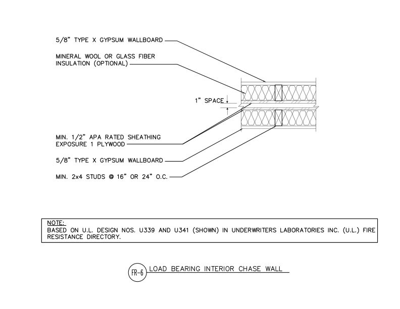
- DT-FR-6
Fire-rated load bearing interior chase wall assembly with gypsum wallboard, plywood sheathing, insulation cavity, and 1-inch space between stud walls at 16- or 24-inch centers.
Typical Details
- DT-FR-6
Fire-rated load bearing interior chase wall assembly with gypsum wallboard, plywood sheathing, insulation cavity, and 1-inch space between stud walls at 16- or 24-inch centers.
 Typical Details
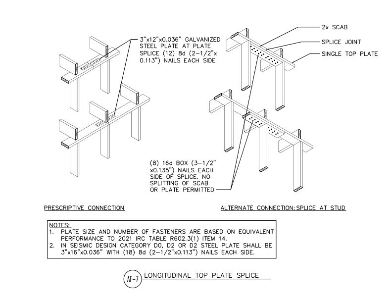
- DT-AF-7
Typical Details
- DT-AF-7
 Typical Details
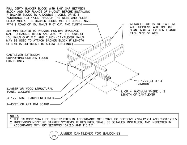
- DT-IJ-7
This detail outlines a construction method for balconies using cantilevered lumber extensions attached to I-joists at their back span.
Typical Details
- DT-IJ-7
This detail outlines a construction method for balconies using cantilevered lumber extensions attached to I-joists at their back span.
 Typical Details
- DT-GB-14
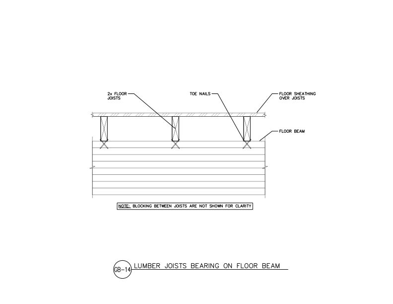
This detail shows a cross-section of sawn lumber floor joists secured by toe nails supported by a glulam beam.
Typical Details
- DT-GB-14
This detail shows a cross-section of sawn lumber floor joists secured by toe nails supported by a glulam beam.
 Typical Details
- DT-SPR-12
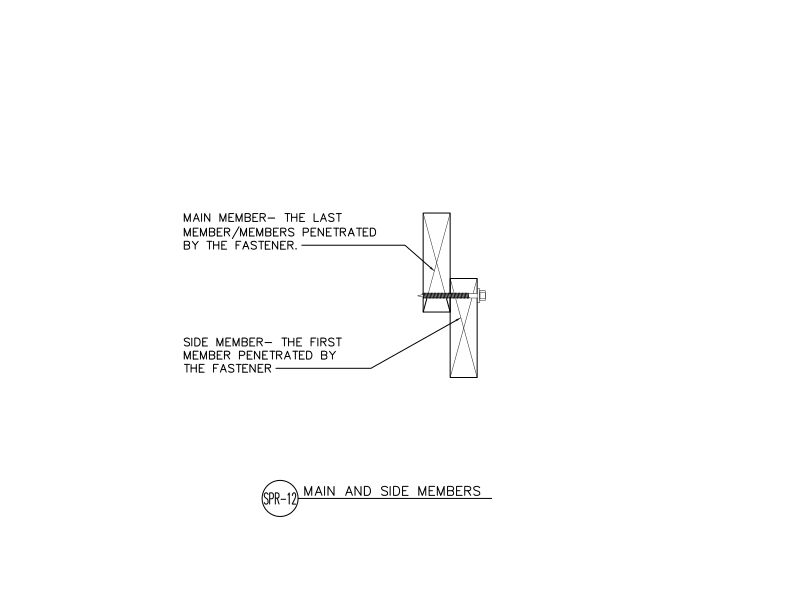
This detail shows fastener connection between main member (last member penetrated) and side member (first member penetrated) in wood construction.
Typical Details
- DT-SPR-12
This detail shows fastener connection between main member (last member penetrated) and side member (first member penetrated) in wood construction.
 Typical Details
- DT-WB-2
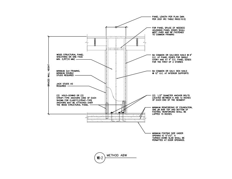
This detail shows the alternate braced wall bracing method and its requirements including sheathing fastening, framing requirements, and foundation anchorage.
Typical Details
- DT-WB-2
This detail shows the alternate braced wall bracing method and its requirements including sheathing fastening, framing requirements, and foundation anchorage.
 Typical Details
- DT-WB-4
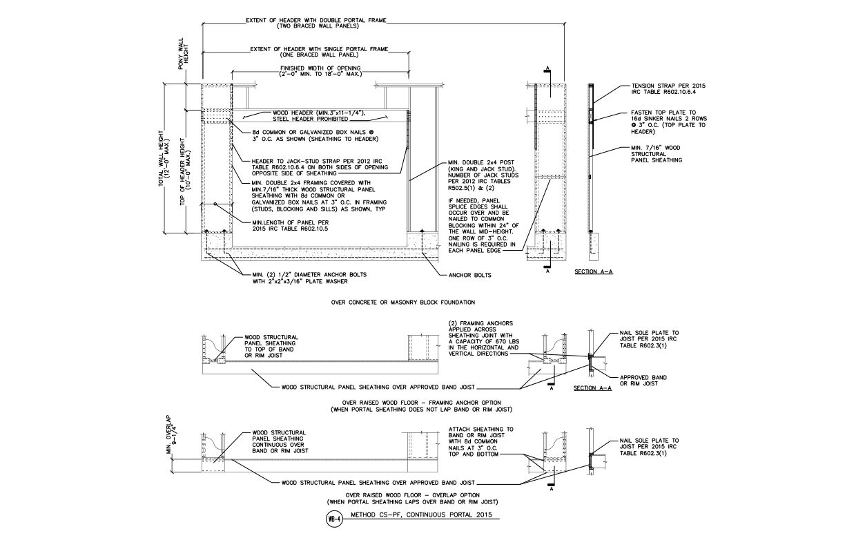
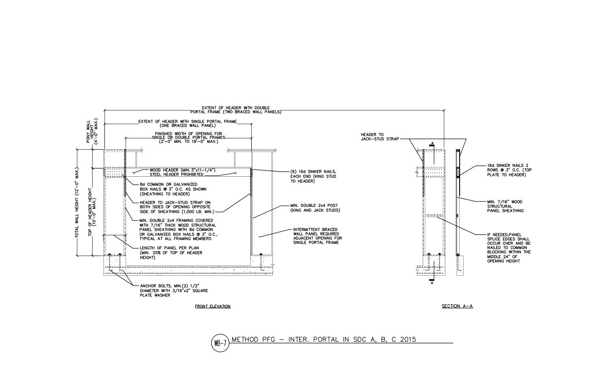
This detail shows the wall bracing method continuously sheathed portal frame and its requirements including anchorage, minimum member sizes, and sheathing attachment.
Typical Details
- DT-WB-4
This detail shows the wall bracing method continuously sheathed portal frame and its requirements including anchorage, minimum member sizes, and sheathing attachment.
 Typical Details
- DT-WB-7
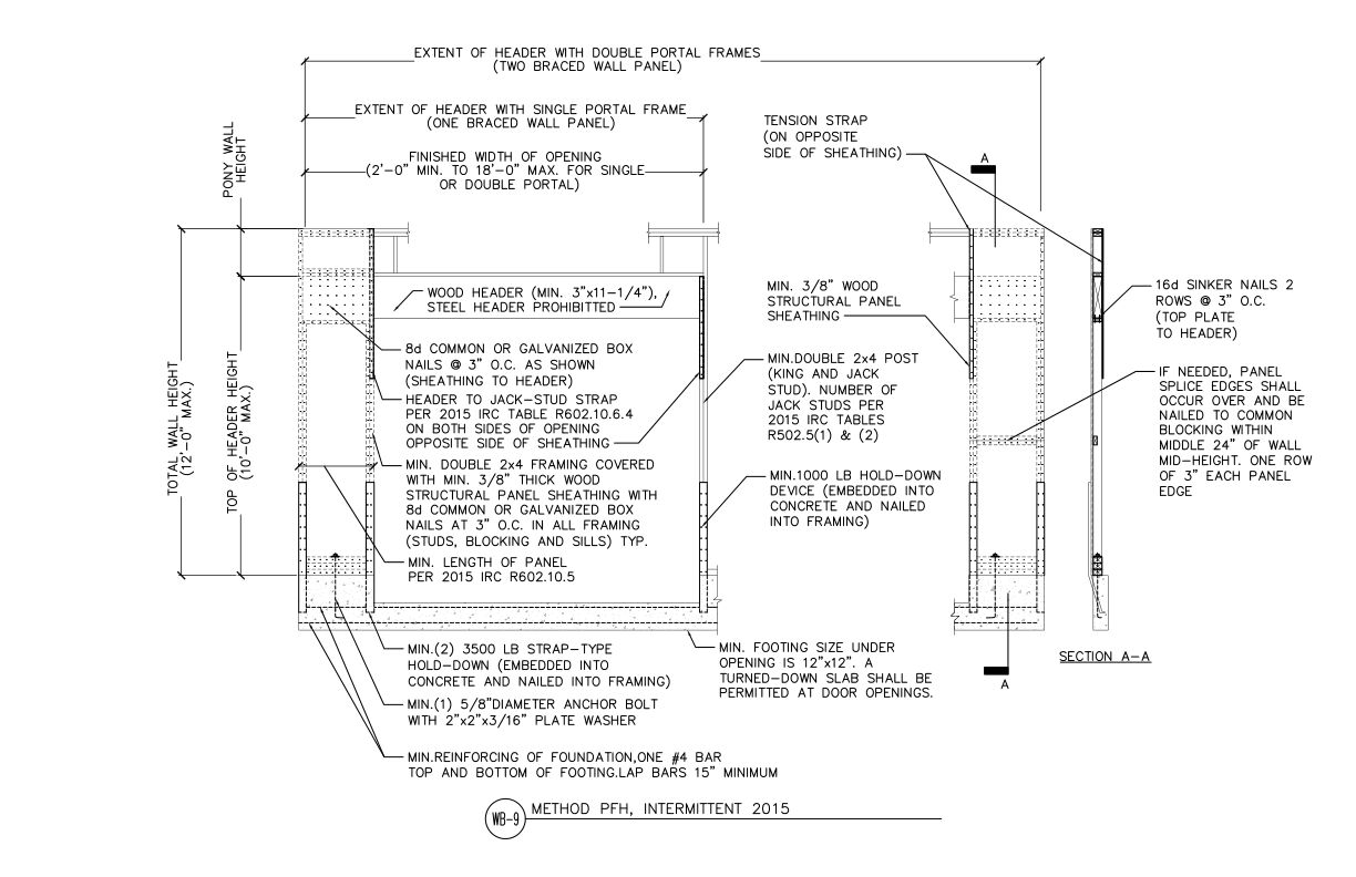
This detail shows the wall bracing method portal frame at a garage and its requirements including sheathing attachment, minimum member sizes, and anchorage.
Typical Details
- DT-WB-7
This detail shows the wall bracing method portal frame at a garage and its requirements including sheathing attachment, minimum member sizes, and anchorage.
 Typical Details
- DT-WB-9
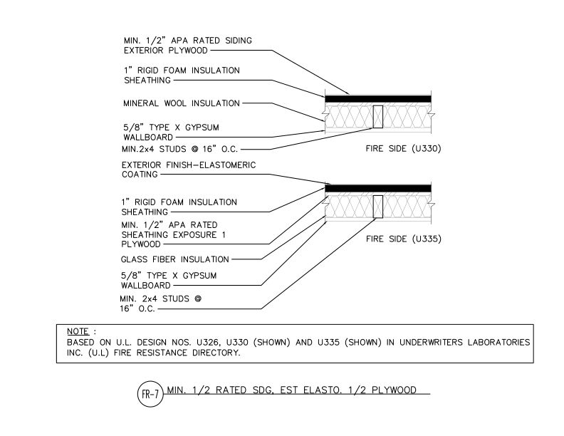
This detail shows the wall bracing method portal frame with hold down and its requirements including minimum framing sizes, sheathing attachment, hold-downs, and anchorage.
Typical Details
- DT-WB-9
This detail shows the wall bracing method portal frame with hold down and its requirements including minimum framing sizes, sheathing attachment, hold-downs, and anchorage.
 Typical Details
- DT-FR-7
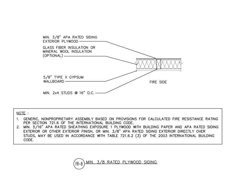
Fire-rated wall assembly of two UL-rated configurations (U330 and U335) with different exterior finishes over wood framing with mineral wool or glass fiber insulation.
Typical Details
- DT-FR-7
Fire-rated wall assembly of two UL-rated configurations (U330 and U335) with different exterior finishes over wood framing with mineral wool or glass fiber insulation.
 Typical Details
- DT-FR-8
This detail shows fire-rated wall assembly detail of 3/8" APA rated plywood siding over Type X gypsum wallboard with optional insulation on 2x4 studs at 16" on center.
Typical Details
- DT-FR-8
This detail shows fire-rated wall assembly detail of 3/8" APA rated plywood siding over Type X gypsum wallboard with optional insulation on 2x4 studs at 16" on center.
 Typical Details
- DT-WOM-1
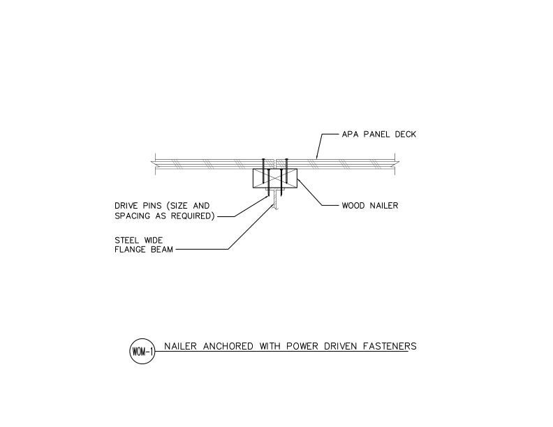
This detail shows wood nailer attachment to steel wide flange beam using drive pins to support APA panel deck, secured with power driven fasteners.
Typical Details
- DT-WOM-1
This detail shows wood nailer attachment to steel wide flange beam using drive pins to support APA panel deck, secured with power driven fasteners.
 Typical Details
- DT-SPR-13
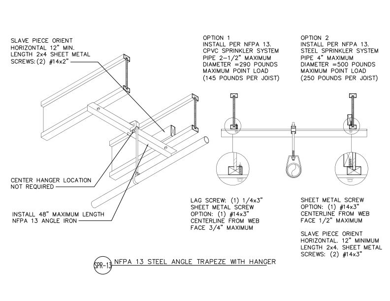
This detail shows steel angle trapeze hanger system for supporting CPVC or steel sprinkler pipes from wood joists per NFPA 13 requirements with two installation options.
Typical Details
- DT-SPR-13
This detail shows steel angle trapeze hanger system for supporting CPVC or steel sprinkler pipes from wood joists per NFPA 13 requirements with two installation options.
 Typical Details
- DT-EWG-26
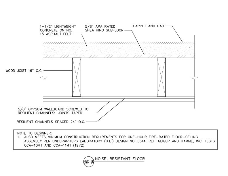
This detail shows noise-resistant floor/ceiling assembly using APA Rated sheathing subfloor, lightweight concrete topping, resilient channels, and gypsum wallboard.
Typical Details
- DT-EWG-26
This detail shows noise-resistant floor/ceiling assembly using APA Rated sheathing subfloor, lightweight concrete topping, resilient channels, and gypsum wallboard.
 Typical Details
- DT-EWG-27
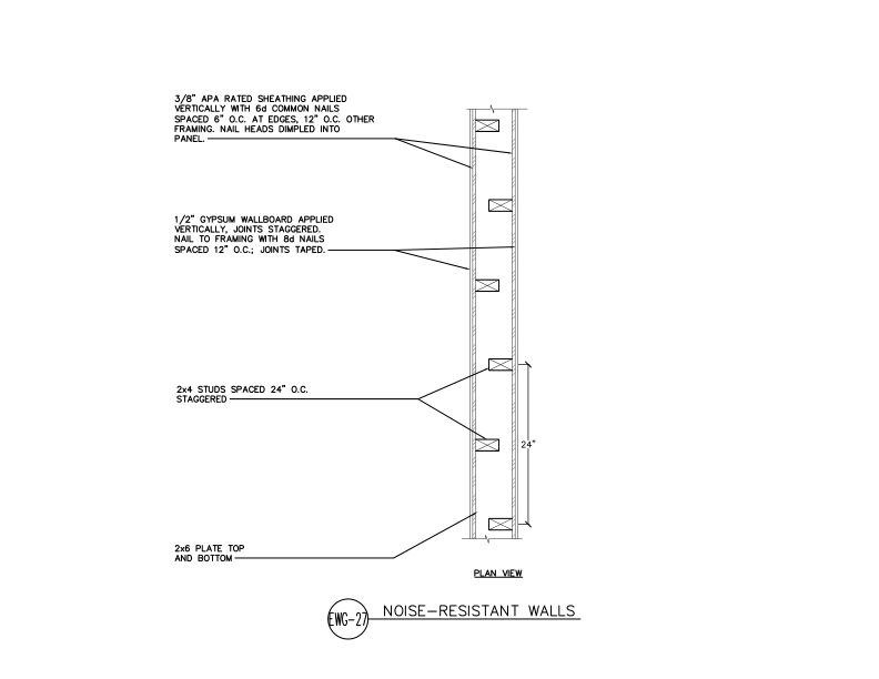
This detail shows a noise-resistant wall assembly in plan view using staggered 2x4 studs on 2x6 plates with APA Rated sheathing and gypsum wallboard to reduce sound transmission.
Typical Details
- DT-EWG-27
This detail shows a noise-resistant wall assembly in plan view using staggered 2x4 studs on 2x6 plates with APA Rated sheathing and gypsum wallboard to reduce sound transmission.
 Typical Details
- DT-SPR-14
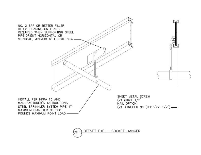
This detail shows installation of an offset eye-socket hanger supporting a 4-inch steel sprinkler pipe with filler block bearing and fastening requirements.
Typical Details
- DT-SPR-14
This detail shows installation of an offset eye-socket hanger supporting a 4-inch steel sprinkler pipe with filler block bearing and fastening requirements.
 Typical Details
- DT-EWG-28
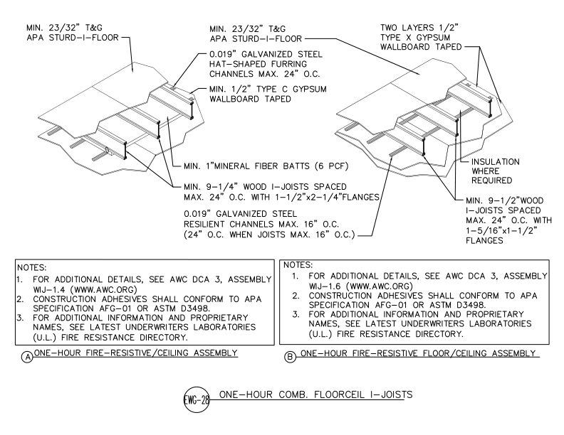
This detail shows one-hour fire-resistive floor/ceiling assemblies using wood I-joists with APA Sturd-I-Floor decking and gypsum wallboard ceiling systems with furring channels.
Typical Details
- DT-EWG-28
This detail shows one-hour fire-resistive floor/ceiling assemblies using wood I-joists with APA Sturd-I-Floor decking and gypsum wallboard ceiling systems with furring channels.
 Typical Details
- DT-EWG-29
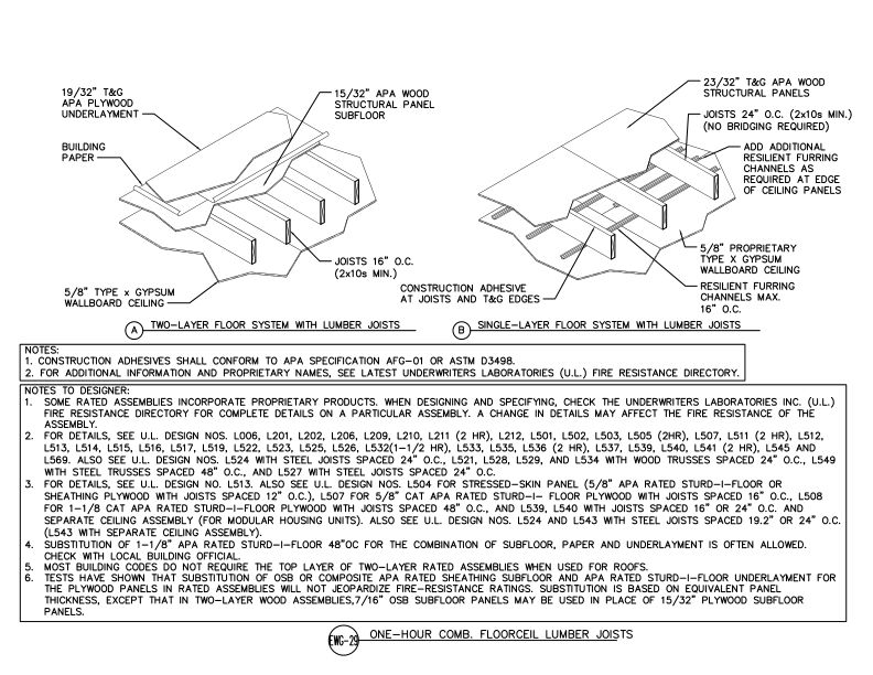
This detail shows two one-hour fire-rated floor/ceiling assemblies with lumber joists.
Typical Details
- DT-EWG-29
This detail shows two one-hour fire-rated floor/ceiling assemblies with lumber joists.
 Typical Details
- DT-EWG-30
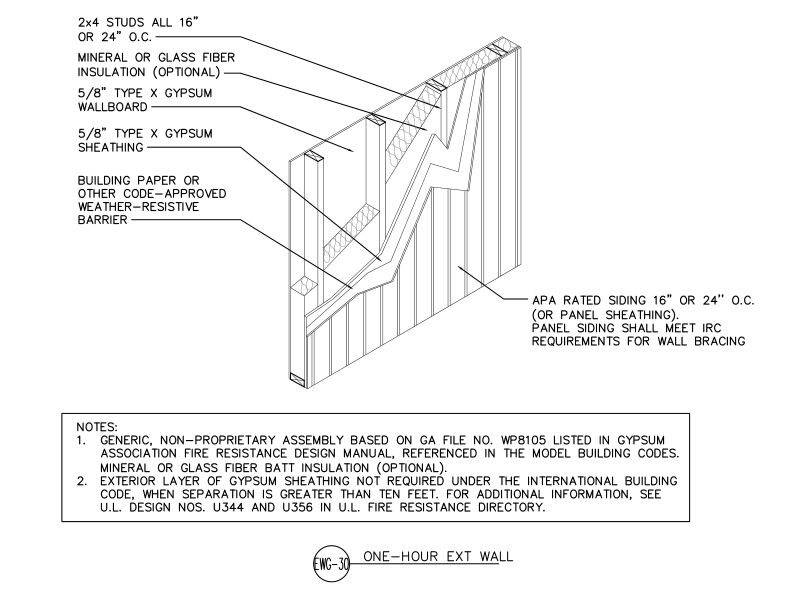
One-hour fire-rated exterior wall assembly using APA Rated siding, gypsum sheathing, weather-resistive barrier, and Type X gypsum wallboard over 2x4 wood stud framing.
Typical Details
- DT-EWG-30
One-hour fire-rated exterior wall assembly using APA Rated siding, gypsum sheathing, weather-resistive barrier, and Type X gypsum wallboard over 2x4 wood stud framing.